The flow of electrons is the charge. We are already aware that 6.242 electrons make up 1 coulomb of charge. When there is a source of voltage in a material, the electrons will be positioned due to the potential difference created by the chemical action of the battery, the electron will drift towards the positive side of the battery and in so doing will collide with atoms as they drift towards the positive side.
These collisions result in loss of energy by the electrons, and thus their movement is impeded. This restriction varies and is determined by the type of material. The property of a material that blocks the flow of electrons is called resistance, designated with an R.

When a current flows through any material that has resistance, heat is generated by the collisions of electrons and atoms. That is why a wire that has some level of resistance becomes warm whenever current is passed through it.
We can, therefore, say resistance is the opposition to current. It has its application in the electronic circuit where it is used to prevent current from reaching some parts of the circuit. It is also applied in the design of immersion heat, incandescent bulb, etc.
A basic electrical circuit is an arrangement of the physical component which uses voltage, current and resistance to perform some useful function. An electric circuit consists of a voltage source, a load and a path for current between the source and the load.
Anyone with a little idea of electricity must at one time come across Ohm’s law, stressing its importance in the study of electrical engineering.
George Simon Ohm (1787-1854) was a professor of mathematics and physics who did series of experiments in voltaic cells and conductors. These experiments encompass the effects of temperature on the resistivity of metals.
Ohm’s law states that for any given potential difference, the amount of current produced is inversely proportional to the resistance, which in turn is dependent upon the composition of the wire.
Mathematically, it can be stated as V=IR
The simplicity of Ohm’s law is impressive, almost unbelievable; this is exactly what happened when Ohm first published his results. He was mocked and ridiculed, and the aftermath was his resignation from his professorship. Fourteen years later, he was reinstalled and was given the accolade and recognition due to him.
During Ohms time, the experimental verification of his law was actualised using direct current sources otherwise called voltaic cells. It has also been proven from further experimentation since then, that the law is still valid when the potential difference across a linear resistor is time-varying.
In the course of studying electrical engineering, you may come across a situation where the volt-ampere characteristics are not linear in which case the current is not related to potential difference by a constant proportionality factor. In this case, Ohm’s law can be expressed in the differential form:dv=Rdi.
It is interesting to note that even though ohm’s law applies to many materials which include: copper, aluminium, iron, tungsten, brass, bronze etc., which is not the case with all. For example, it does not apply to nonlinear devices involving step discontinuities such as might be found in Zener diodes and voltage regulators.
Gustav Robert Kirchhoff (1824-1887) published the first systematic formulation of the principle guiding the behaviour of electric circuits. His work was embodied in two laws- a current and a voltage law which make up the Kirchhoff’s law.
Kirchhoff’s voltage law states that at any time instant, the algebraic sum of the potential rises and drop in a closed loop, mesh or circuit is equal to zero.
A closed loop is any continuous path that leaves a point in one direction and returns to that same position from another direction without leaving the circuit.
This law can be stated in another way to mean that the algebraic sum of the potential rises and drop must equal to zero.
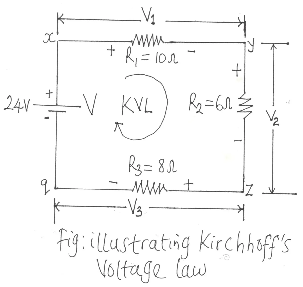
We will assign positive sign (+) to potential rise, and a negative sign (-) will be used to depict the potential drop. The concept of potential rise and drop is quite simple. It has it that for batteries, the current will leave from the positive side while for passive elements like resistors, the current will enter through the positiv side and leaves the element through the negative side. This line of thought is illustrated in the figure below when we assume clockwise flow of current while considering the pressure from the battery source.
Consider the closed loop of the diagram shown below . Following the current, we can trace a continuous path that leaves point x through R1 and returns through q without leaving the circuit. Thus,qxyz is a closed loop.

For us to successfully implement KVL, the summation of the potential rises and drops must be made in either clockwise or anticlockwise direction, and we have to be consistent about it.
We will be using clockwise direction all through our examples here.
For uniformity, the clockwise (CW) direction will be adopted but, it is also good to know that we will still achieve the same result if we are to go anticlockwise and maintain it consistently.
A plus sign is given to a potential rise (- to +) and a minus sign to a potential drop (+ to -).
If we follow the current in the figure above starting from point a, we will first meet a potential drop V1 (+ to -) across R1 (+ to -) and then another potential drop V2 across R2 (+ to -). As we progress, we will meet another potential drop V3 across R3 until we get to the voltage source V (- to +) which is a potential rise before returning to where we started the journey which is point x.
In the symbolic form where Σ represents summation, o will represent a closed loop, and v depicts the potential drops and rises, we will have: ΣoV =0 (Symbolic representation of Kirchhoff’s voltage law).
For the circuit under consideration
V- V1- V2- V3=0
V= V1+ V2+ V3
This reveals that the applied voltage of a series circuit is equal to the summation of the voltage drops across the series elements.
In other words, Kirchhoff’s voltage law can be stated regarding potential rises and drops’
In that case, one can say that the sum of the potential rises must be equal to the sum of the potential drop in a closed loop.
ΣoVrises = ΣoVdrops
We can still analyse the above circuit with regards to work done per unit charge and still arrive at the same conclusion.
Since the current that flows through the circuit is of constant value, it, therefore, means that the average rate of movement of charge is constant.
But as the electron moves through the circuit elements, R1, R2 and R3, they will experience collision with atoms in the space lattice configurations of these elements with consequent dissipation of energy in the form of heat.
Since the battery supplies the energy, the law of conservation of energy will allow us to write:
W= W1 + W2+ W3 ; W denotes the energy supplied by the battery in a given time interval. W1 denotes the energy dissipated in R1 in the same time interval and the same goes for W2 and W3.
Furthermore, if the total charge which transverses through the circuit is Q, It follows that the work per unit charge can be written as:
W/Q= (W1)/(Q1)+ (W2)/(Q2)+(W3)/(Q3)
Work done per unit charge is the voltage, thus
V= V1 + V2 + V3
This result proves to be the same as what we got earlier.
Kirchhoff’s current law states that the sum of the current entering or leaving a junction or node at any instant is equal to zero. A junction point is that place in a circuit where two or more circuit element are joined together
Kirchhoff’s current law can be restated as the sum of the currents entering an area, system or junction must equal the sum of the current leaving the area, system or junction.
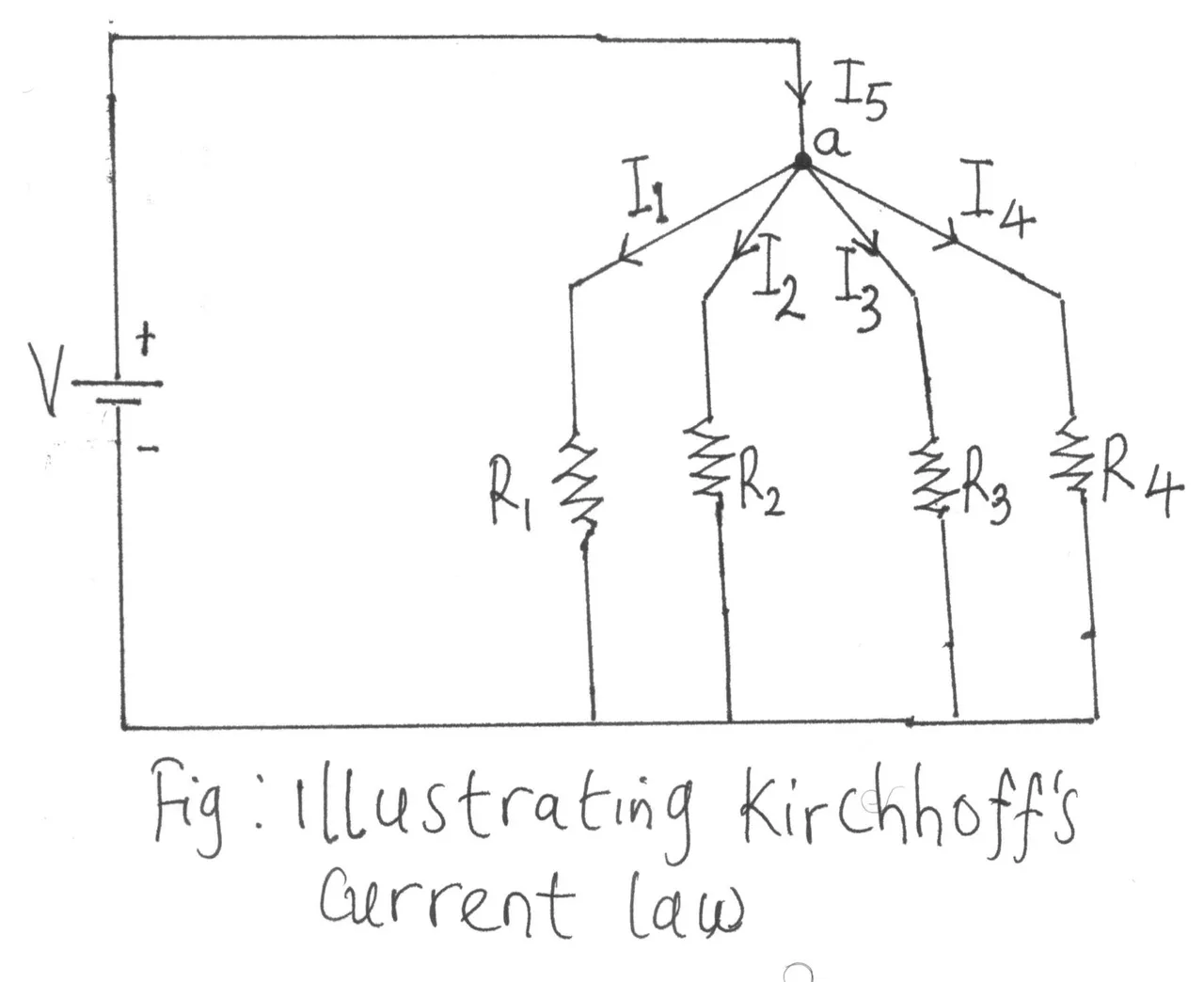
Consider the diagram below:

I5 = I1 + I2 + I3 + I4
Σentering = Σleaving
In the countless experiment performed over the years, Kirchhoff’s law has stood the test of time and is still valid up till today. As long as the law of conservation of charge holds, Kirchhoff’s law will continue to be relevant because it is just a restatement of the laws of conservation of charge.
The principle states that the number of electrons passing per second must be the same for all points in the circuit. In the same vein, if the currents at a node were not to add up to zero, there would be a resultant accumulation of charges at the node which will result in an explosion.