In the early days of transmission of AC electric power, transmission and distribution are predominantly done using copper as conductor material owing to its excellent conductivity. Nowadays, aluminium has wholly shown dominance and has virtually replaced copper for overhead lines because of its lower cost, lighter weight and the larger diameter of aluminium for the same conductivity that will be offered by copper.

The more significant diameter of aluminium for the equal resistivity as copper will give further puts aluminium ahead in desirability because, with a larger diameter, the lines of electric flux emanating from the conductor will be farther away from each at the conductor surface for the same voltage. The larger separation of this electric flux means that there will be lesser potential gradient at the surface of the conductor resulting in lesser tendency to ionise the air surrounding the conductor. We need to recollect that overhead line conductors are bare ant it is air that serves as insulation for it.
When the air is ionized, the result will be corona which causes power loss and interference with the nearby communication circuits and the effect is not desirable.
In the precursor to this post we took time to highlight the different attributes of an ideal conductor before we all come to a conclusion that it is almost impractical for a single conductor to come close to the ideal status without modification.
The examination of the atomic structure of copper and the number of free electrons that is in a square meter of copper dwarfed that of aluminium, and as such, it is a better conductor, but when you look at cost, radius, specific gravity, availability, you will appreciate why aluminium is more popular.

Since application of these conductor materials differs with the prevailing condition in which they will find themselves and the specific duty in which they will be called upon to perform, it becomes imperative to modify these conductors to suit the purpose of which they are to serve.
Special (Modified) Conductors
There comes a time when the construction of a conventional conductor can be modified to enhance its performance under certain conditions. It may be desirable to have the conductor exhibit the following properties:
- Increased thermal rating
- Increased self-damping ability to dissipate Aeolian vibrations
- Increased line tension to reduce sag.
The worst possible condition for an overhead line results at low temperature where the conductor contracts and shortens in length and this increases the tension in the conductor, the addition of wind and ice loads further aggravates the tension on the conductor. Thus, the conductors experience forces as a result of its weight, wind force and ice loading.
When a conductor is stringed between two supports, it experiences tension with a threshold beyond which if the pressure surpasses will exceed its ultimate strength and with consequent failure. The ultimate strength of a conductor is dependent on conductor material used for the overhead line.
The tension in a conductor has a direct relationship with the diameter of the conductor, the length of span between supports, conductor material, and sag in conductor, wind force and temperature. Loading conditions and temperature variations govern this relationship between sag and tension, and as such, we experience a decrease in tension with an increase in temperature as a result of the conductor expansion. On the hand with increased ice and wind loading, the conductor stretches out the conductor to an extent governed by wind loading.

The modification in the characteristics of these conductors is electrical, mechanical and thermal. We will look at the different factors that affect the sag of an overhead transmission line and the different ways of averting it using modifying the characteristics of the conductor.
Sag is the difference in height between the point the conductor is attached to the support (which could be pole, lattice structure etc.) and the lowest point in the conductor. This lowest point in the conductor is at the mid-point for conductors stringed on supports standing on level ground.
The factors that influence the sag on transmission lines includes:
The weight of the conductor: This affects the sag because the weight of the conductor acts vertically downwards and as a result the heavier the conductor, the more significant the sag.This property of the conductor entails that there is need to modify the conductor to have a way of offering a lesser area to wind load or having the property of damping out the effect of the wind that will result. Another consideration is that of ice loading when the conductor has a larger cross-section for a given resistance or conductivity; the larger exposed surface area will offer more area for ice deposits resulting in more substantial sag and tension on the conductor.
Length of Span: Sag is directly proportional to the length of the span as given by the formula below;
S=(wl2)/8T
where S stands for sag for conductor strung on support on the equal level ground
w stands for the weight of the conductor
L stands for the length of the span
T stands for tension in the conductor which is assumed to the uniform throughout the cross-section of the conductor.
When all other conditions like temperature, type of conductor, working tension remain the same, a longer span will experience a higher sag.
- Working tensile strength: Sag is inversely proportional to the working tensile strength.
- Temperature: All metals undergo expansion with increase in temperature resulting in an increase in the length of the conductor with the rise in temperature which goes the same with the sag of the conductor.
The sag plays a vital role in the design of an overhead line. Providing too high or too low a sag comes with its advantages and disadvantages. If the sag is too high, you will notice that an excess of conductor material will be needed for a specific span as opposed to when a low sag is chosen. High sag puts extra load on the support, needs taller support to provide enough clearance for safety from the ground and it is prone to greater swing-amplitude as a result of wind load.
On the other hand, having low sag means that there will be savings in conductor material but on the flip side, the conductor is susceptible to breakage if by any means an additional load is to be taken such as is experienced in fall in temperature or due to vibration.
Aeolian Vibration
Aeolian vibration is one of the problems of overhead lines that cannot be overlooked in overhead line construction and it constitutes the primary source of fatigue failure of conductor strands or other auxiliaries connected with overhead line support such as clamps, cross-arms, insulators or other items associated with the use and operation of the conductor.
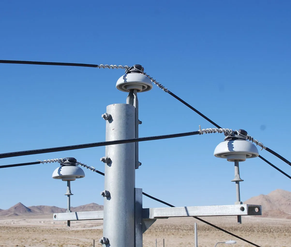
Conductors are held onto insulators mounted on cross-arms using clamps and overtime there results in fatigue at the point where the suspension clamps are used to attach the conductor to the insulator. This phenomenon known as aeolian vibration can also occur from braces of other accessories installed on the conductor which may be in the form of spacers, spacer dampers, dampers or other devices.
This phenomenon is not is not prevalent in stranded conductors as compared to solid conductors, and this is so because the effect is cushioned by the movement of the strand relative to each other and this movement is possible because of the existence of space between the strands. This movement of strand relative to each other helps the conductor to consume the energy of the vibration when it is twisted, majorly as a result of friction between the strands as the glide relative to each other. The energy that will be dissipated increases with increase in frequency, amplitude and the diameter of the conductor because of more wind loading.
The self-dissipation of a conductor is directly related to the tensile stress and as an outcome, the higher the tensile stress, the more compacted the layers of the strands will be packed. The strands will be locked; as a result, there will be less inter-strand friction, which is the primary way in which the self-dissipation takes place when the vibration pushes or bends the conductor into a curved position.
The endurance limit of a conductor is related to the number of strands that are broken as a result of fretting between different layers of strands at the place where they are clamped to the support (contact area).This effect results in cracks which propagate and will eventually lead to failure due to fatigue.
The modification may come in the form of:
- Differently shaped strands
- The degree of the temper of the aluminium strands. Different types of coating for corrosion protection of the steel core in composite cables.
- Or the modification of the geometric configuration of the conductor to produce varying profile to wind.
These modifications may be used in isolation or in combinations to achieve the desired conductor properties for optimum performance.
All-Aluminum Conductor Trap-Wire, (AAC/TW)
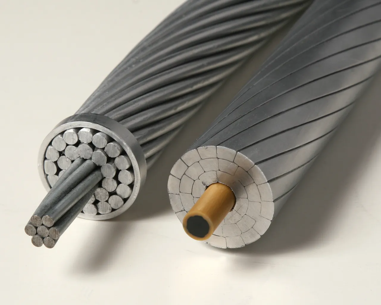
Trapezoidal wire (TW), called trap-wire, deviates from the conventional conductor construction by having strands shaped in the form of a trapezoid. AAC/TW is attractive for the following reasons:
• Reducing the conductor diameter for a given resistance
• Or decreasing the resistance for a given diameter.
Aluminum Conductor Steel-Reinforced Trap-Wire (ACSR/TW)
ACSR/TW differs from the conventional ACSR in that its aluminium strands are formed as a trapezoid. It offers that the advantage of increased current capacity for the same diameter.
Aluminum Conductor Steel-Supported (ACSS)
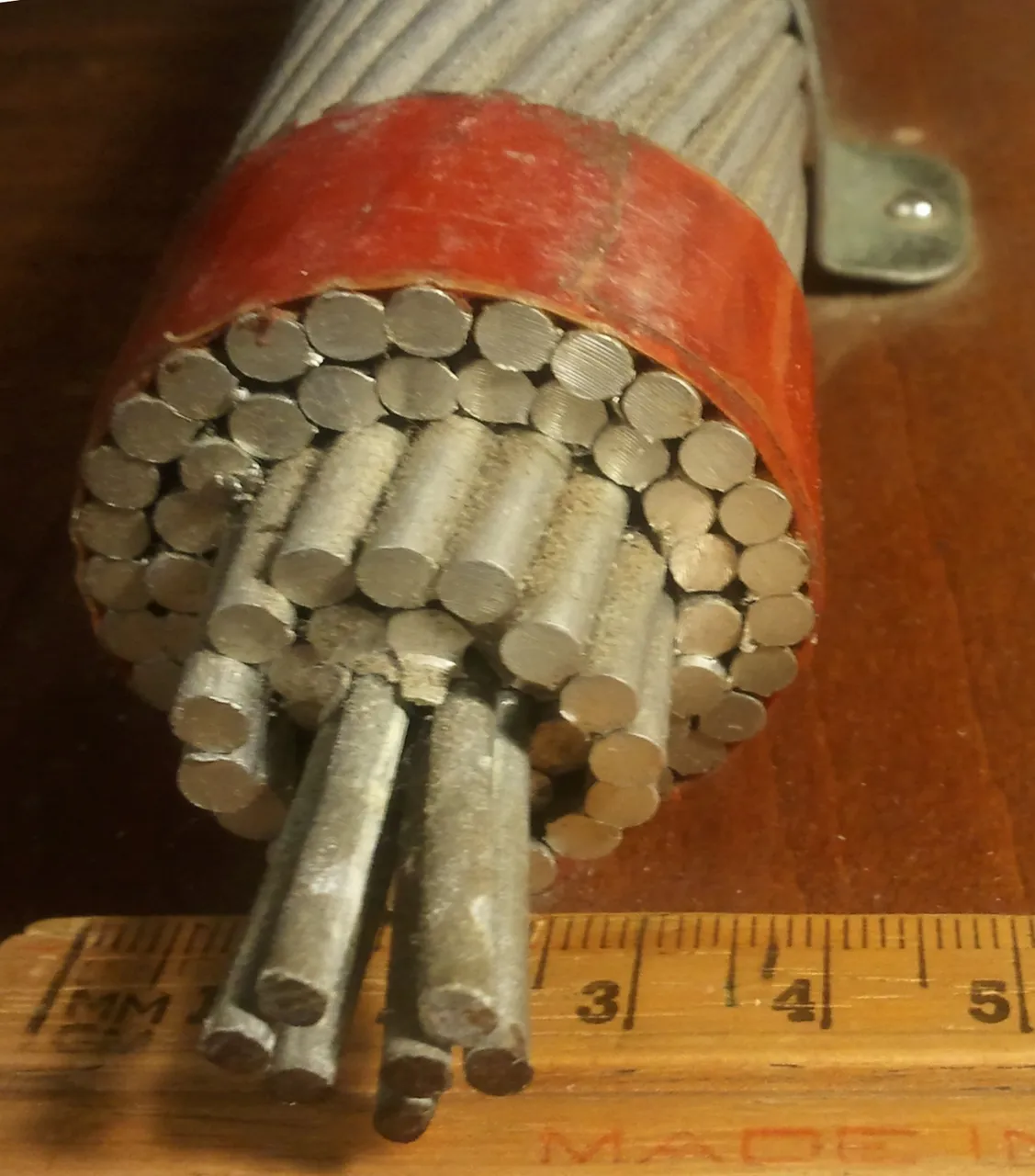
The construction of ACSS is similar to that of regular ACSR with the only difference being that the aluminium strands are fully annealed for ACSS. Under normal operating conditions, ACSS conducts mainly with the steel core. Some of the major advantages of ACSS are:
• ACSS has a high conductivity of 63% IACS or more.
• The conductor can survive at temperatures of over 2000 without loss of strength.
• Since the tension in the aluminium strand is normally low, the conductor´s self-damping characteristics are high.
This attribute allows the conductor to be installed at high-unloaded tension levels without the need for a separate damper.
These properties, along with decreased thermal elongating and creep at elevated temperatures make ACSS attractive for upgrading existing transmission line in an uprating application.

Vibration Resistant Conductor (VRC)
The vibration-resistant conductor finds application in overhead lines normally subject to Aeolian vibration and galloping. Some of the major advantages of vibration resistant cable are:
• The amplitude and frequency of occurrence of galloping due to high winds are reduced or eliminated because of the non-round cross-section.
• The amplitude and frequency induced strains near clamps are reduced because of the varying profile along the length of the conductor. As a result, VRC conductor can be installed to higher tension levels without the need for additional dampers.
Self-Damping Conductor (SDC)
The self-damping conductor is a modification of ACSR construction designed to limit Aeolian vibration by internal damping of the strands. Some of the major advantages that SDC offers are:
• Due to its ability to absorb the effect of vibration by damping it out, there is an improvement in unloaded tension levels, leading to a reduction in sag and structure cost.
• For a given AC resistance, there is a reduction in conductor diameter thereby offering a lesser surface area for wind loads and at the same time reducing structural loading.
Expanded Conductor
Extra high voltage levels, radio interference and corona, can affect the choice of conductor diameter. To limit the surface gradient on the conductor, it is necessary either to use many conductors per phase in the form of a bundle or to increase the diameter of a single conductor per phase. The latter is obtained by omitting some strands within the internal layers.
A filler paper is employed in expanded A.C.S.R., to separate the inner steel strands from the outer aluminium strands. The inclusion of paper offers larger diameter for a given conductivity and tensile strength. It is used for EHV line conductors.

Bundle Conductors
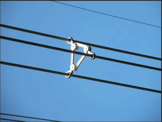
Bundle conductors are conductors having two or more conductors per phase, and it is often separated by spacers to increase their overall diameter. The use of bundle conductors becomes attractive at voltages exceeding 220KV to improve its efficiency and voltage regulation alongside reducing the effect of corona losses.
Several advantages can be obtained by the use of two or more conductors per phase, the major among these are:
- A decrease in line reactance and an increase in capacitance which leads to an improvement in surge impedance loading of the line (i.e. an increase in the power transmission capacity of the line)
- A decrease in surface voltage gradient leading to a reduction in corona losses and radio interference.
- An increase in thermal rating of the line when compared with a single conductor having the same cross-sectional area as the total area of the bundle conductor. It is a fact that several individual conductors will have larger cooling surface than a single conductor of the same overall area
- The amplitude and duration of high-frequency vibration may be halved.
In spite of these benefits, bundle conductor system suffers the following setbacks: - The increase in capacitance often requires correction of the current.
- There is increased ice, and wind loading due to the larger exposed surface area due to larger conductor cross-section.
- Attaching the conductor to the insulator is more complicated, and duplex or quadruple insulator strings may be necessary to hold it firm on the cross-arm as opposed to regular ACSR as a result of the paper filler.
- There is an increase in the tendency to dance.
Based on economic and technological considerations bundle conductors find favour for voltages of about 275kV and higher.
Conclusion
We can never wish away the use of conductors as a means of transmission of power as long as the wireless transmission is still not economical for bulk power transmission. Also like we mentioned earlier, electricity generation is mostly done in outskirts of town or in a remote area where the basic potential for generation is abundant and provided by nature at a reduced cost. In such scenario, we are constrained to generate power there and transport the electricity to the consumer through the vehicle of good conductor capable of keeping the power at the receiving end close that of the sending end.