DESCRIPTION OF A RECTIFICATION COLUMN
It has already been commented that in order for distillation to occur, a stream of vapor (ascending through the column) must be kept in intimate contact with the liquid stream (which descends through it); the larger the contact between both currents, the column will work more effectively. There is a considerable variety of devices to make the contact between these two currents intimate and can be divided into two main types:
· Columns of dishes
· Columns of filling.
The columns of plates are subdivided into:
Columns of bubbling bells and columns of perforated plates.
Columns of bubble bells.

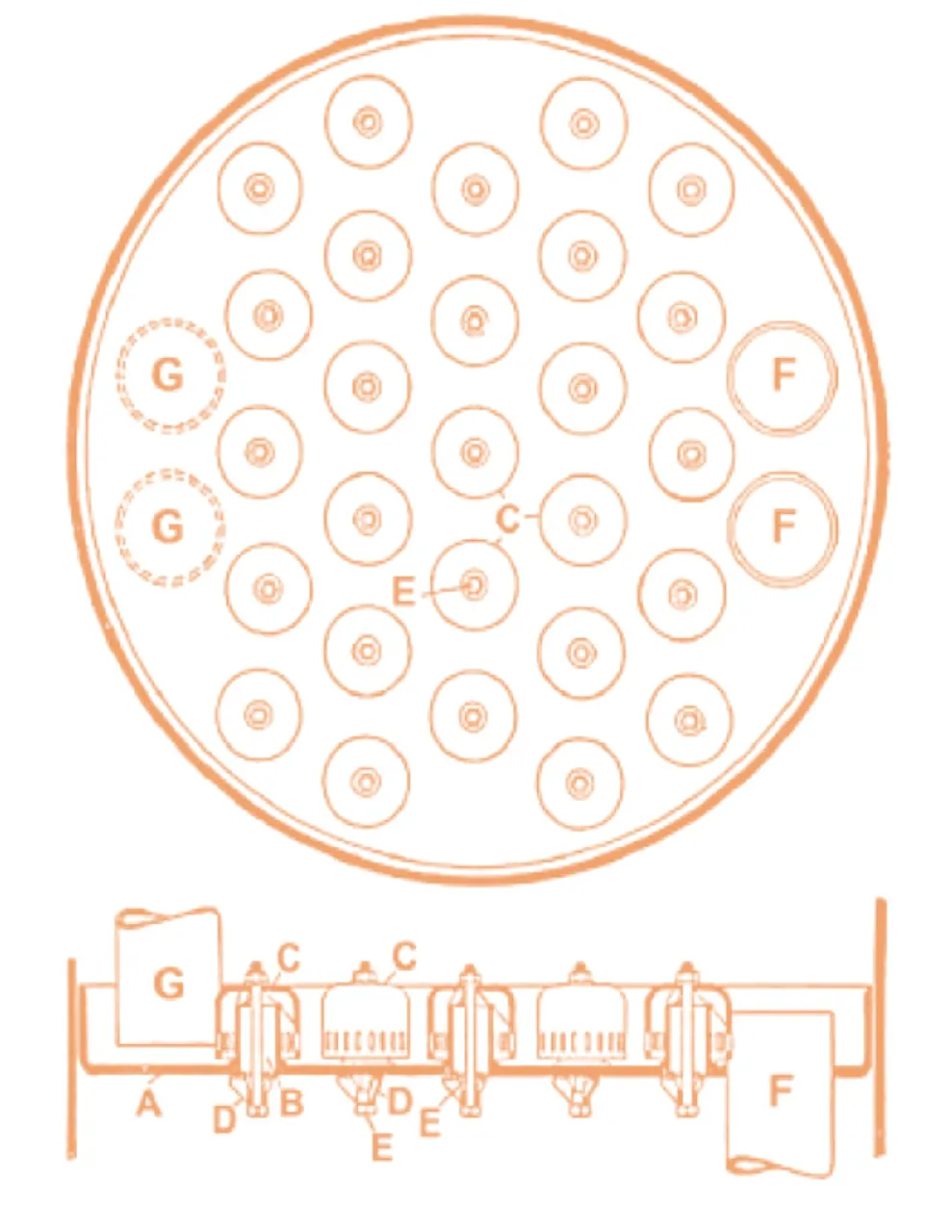
Figure 1 represents the whole of a plate with bubble bells. The column is divided into sections by means of a series of horizontal A plates.
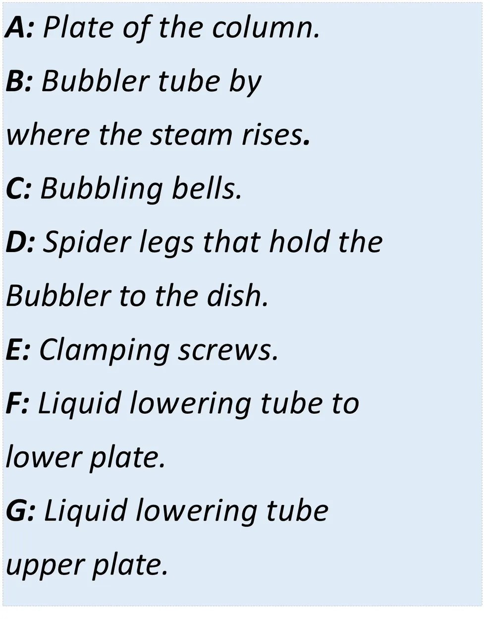
Each plate carries a certain number of short tubes B; each short tube (or vapor riser tube) is covered by a bell-shaped cap C (bubbler bell), which is secured in place by a piece with three legs D and a pin E

The edge of the bubble bell may be toothed or the side walls scored. The steam ascends from the lower plate through the tubes B, is deflected downwards by the bell and comes out in the form of bubbles by the toothing or by the grooves of the bells. A layer of liquid is maintained on the plate by means of the descent pipes F, and the height of the liquid must be such that the grooves remain submerged. The drop tube G, coming from the upper plate, is closed by the liquid on the lower plate so that the steam can not circulate through this pipe. Normally the liquid is fed by the end of a diameter by means of a down tube from the immediately superior plate, it circulates through the plate and is discharged at the other end of the diameter, by means of another down tube, to the immediately lower plate.
In Figure 2, many construction details have been omitted. In the first place, no indication is made about the way in which the plate is placed in its position. The edge of the plate can go but rarely goes, welded to the lower casing. The plate can be riveted to a ring that is welded to the casing. The plates can also be supported by one another through a series of bolts. A wide variety of constructions are used according to the size of the column and the frequency with which repairs are necessary.
Instead of leaving the chimneys unattached in the holes of the plate, as seen in figure 2, they can be borne on the plate or they can be welded to it.