Controlling Hydraulics
Using The Servo / Block / Decomp Stack-Up

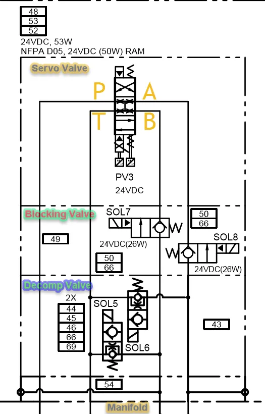
The circuit above may look deceiving, however it is really not that bad. Looking at the diagram let me explain it:
The 'Servo Valve' is the actual control of the cylinder circuit. The valve consists of 4 ports for fluid movement. Port 'P' is the supply pressure. Port 'T' is the drain back to tank. Port A is plumbed to the cap end of a cylinder. Port B is plumbed to the rod end of a cylinder.
The Blocking valve is an electro-mechanical device that closes off the orifice in the respective line. This valve is used to hold the cylinder in a certain position. When the valve is not energized, fluid CAN NOT move through that leg of the hydraulic circuit. In order for motion to happen in a hydraulic system there has to be flow. So in theory, if you block the orifice, fluid can NOT flow, thus the cylinder CAN NOT move.
The 'Decomp Valve' is an electro-mechanical device that opens up the orifice in the respective line. This valve is used to release the stored pressure / energy in a hydraulic circuit. When this valve is not energized, fluid CAN move through that leg of the hydraulic circuit. In theory, the lack of flow creates pressure, to reduce the pressure this valve is used in-line with the tank port. Upon de-energization of the valve, the spool shifts to the open position providing a path for flow to the tank.
So using this circuit, the order for motion would consist of:
A: Energize Decomp Valve
B: Start Pump
C: Energize Blocking Valve
D: Shift Servo To Move Cylinder (Motion)
E: Shift Servo Center (No Motion)
F: De-Energize Blocking Valve
G: Wait For Next Motion Command
H: Upon Motion Completion Stop Pump
I: De-Energize Decomp Valve To Release Pressure
Hope this is clear enough to understand. Comments welcome.
Relay