Repairing Kenmore HE-5 Pressure Switch (F-35 Fault Code)
WASHING MACHINE
Our washing machine (Kenmore Elite Quiet Pak 9 HE-5) recently began punking out on us, always giving either the SUD error, or fault code F35.
After not too much research, I was able to determine that the pressure seitch has likely failed and neds to be replaced - no big deal, right? Well, if you know me, you know I’m going to make a stink about it anyway…because it turns out this little component costs a minimum of $90 and has a typical 3 week lead time.

See that circular cap that looks like a filter housing (below)? Well it is a filter housing. In the past, I’ve had to clear that out (kid socks get sucked in and block it)…but the filter was clear this time (unfortunately).

I should have circled it, but the pressure switch is located in the back right corner (below).

PRESSURE SWITCH


CUT/BURNED OPEN


MY EASY DEFEAT
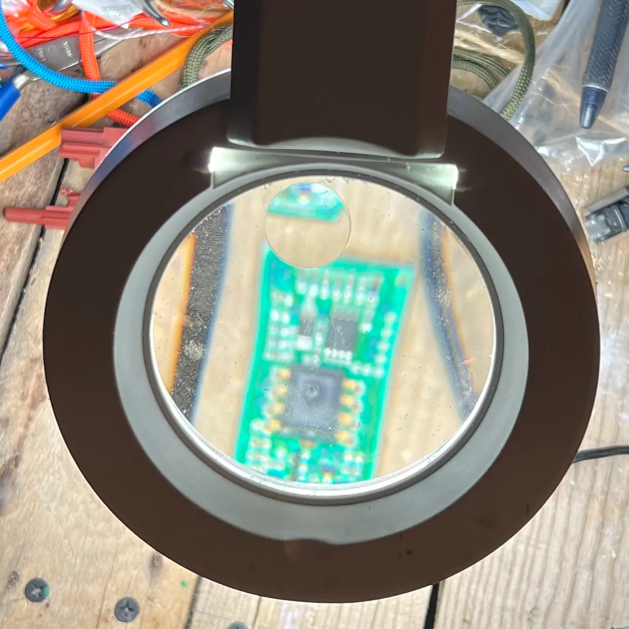
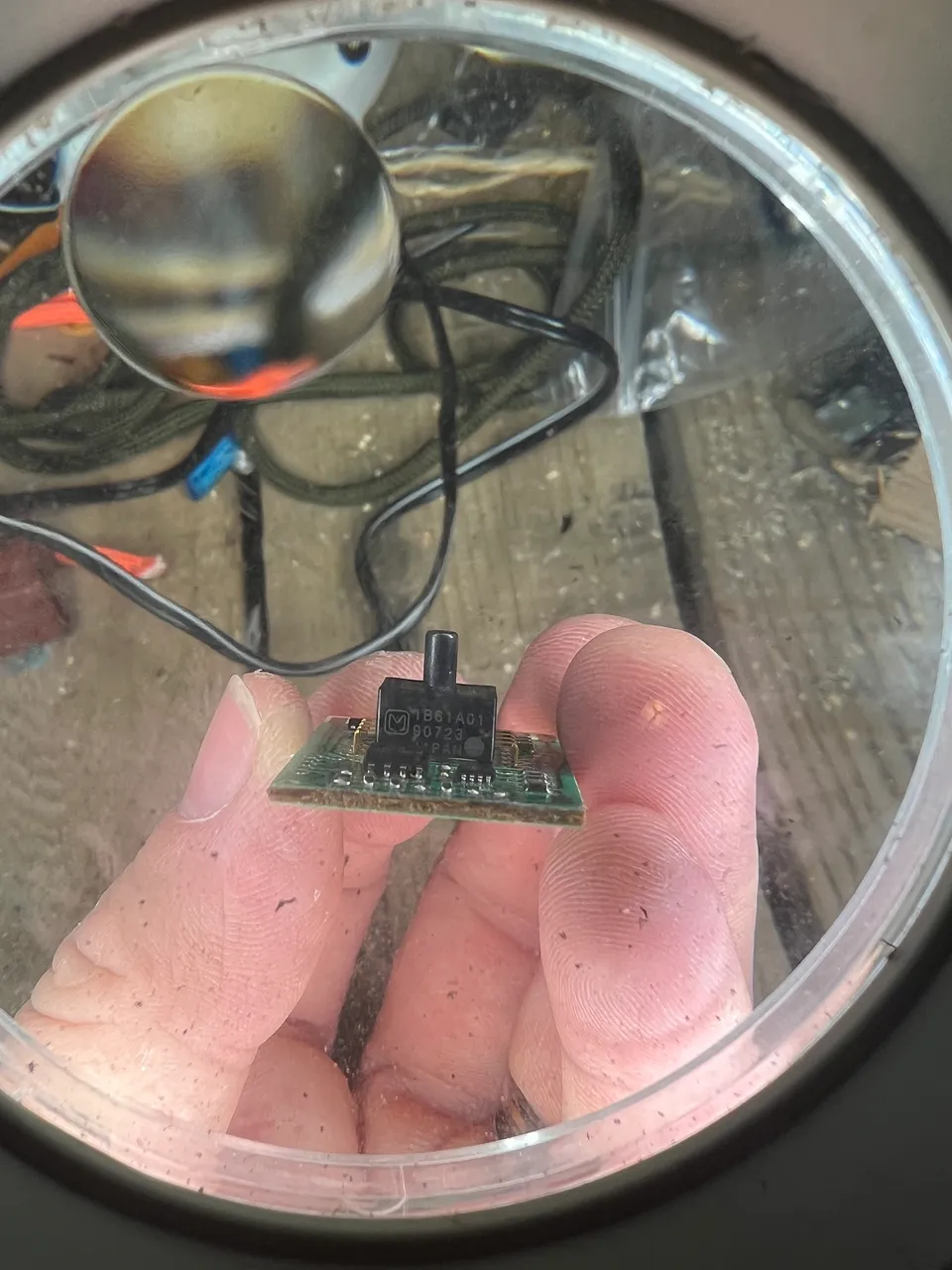
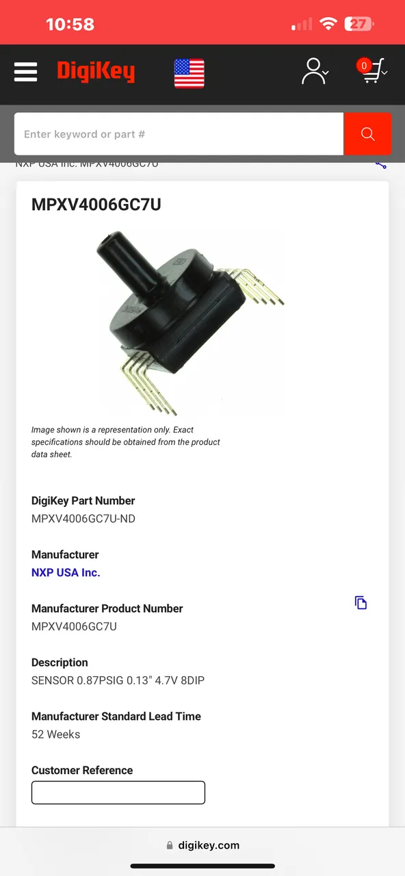
After much searching online, I am still unable to locate this part. I found an 8-pin pressure switch IC on Digikey, but the form factor was not identical and the PN didn’t match, so i really can’t be sure that the pinout is the same.


This was the closest I found, but even though it has 8 pins, the body is round and has a lower profile.

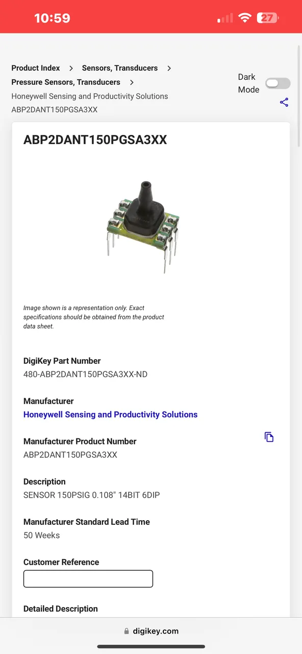
The next best option didn’t have enough pins, so not likely to be a viable replacement.
I reviewed hundreds of parts, but there was no solid match, and even if there was, by the time I paid for parts and shipping, it would be almost the same as buying a replacement assembly, so I went ahead and ordered one…
…but the new pressure sensor didn’t fix the issue, so I began to look a little deeper.
From what I found, it looks like this issue is caused either by a bad pressure sensor ($100), or a bad control board ($400), and by this point we have eliminated the pressure sensor - but I can’t bring myself to buy a part that costs as much as a washing machine, so I looked into possible reasons that the control board would fail.
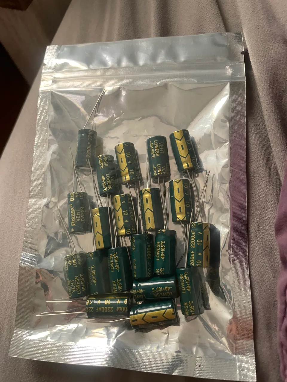
I found that there are two 10V 2200uF capacitors that tend to be what dies first on these boards, and I can easily at least try this becuase these parts don’t tend to cost much - so if it doesn’t work it’s not a huge loss but if it does, I’ve just saved a lot of money :)


In fact, I got 20 of these capacitors for $8! So if this really is the failure point, I should be able to repair this issue 9 more times after this for basically no extra cost - man I hope this works!!!
REPLACING THE CAPACITORS
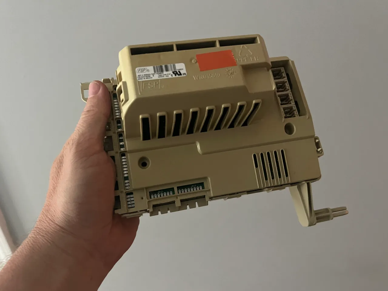
Aside from the small sensor board assembly there are two larger circuit board assemblies. I wasnt sure which was the main control board (although I had a feeling…), so I took out the easiest board first…
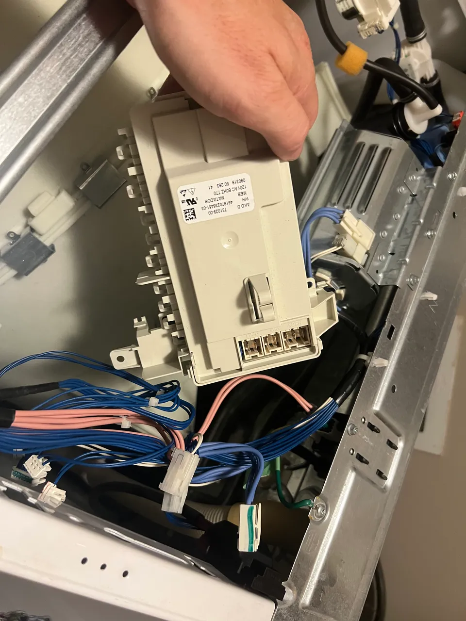
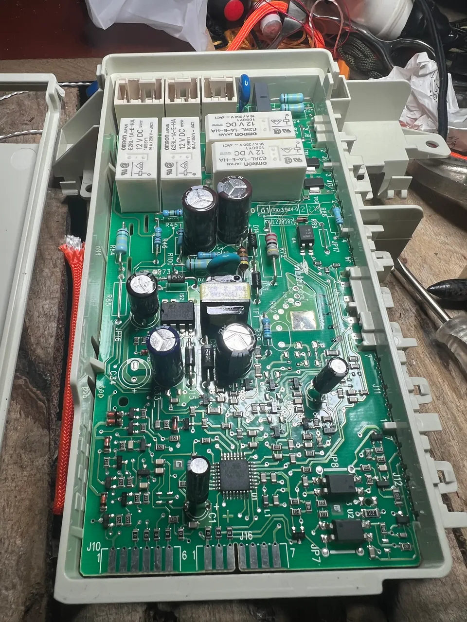
…these caps are all fine, and there are no 2200uF’s on here. Unfortunately, my suspicions were correct - the hard-to-remove board is the board I seek :(

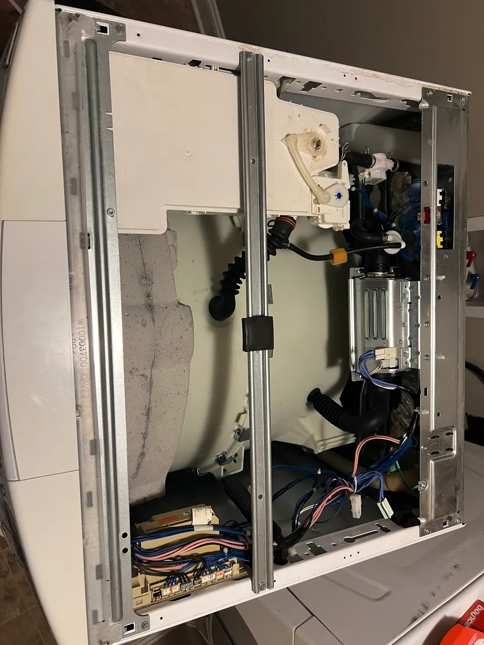
After dorkin’ around with thr plastic housing and coming no closer to determining how to carefully remove it, I decided that the overhead crossbars must need to be removed.

Once the crossbar was out, it became clear that I was no closer to understanding how to remove the PCB housing, so I didnwhat any responsible washing machine owner would do: I snapped off the useless extra plastic from the top of the housing to get a better view…stupid extra plastic!
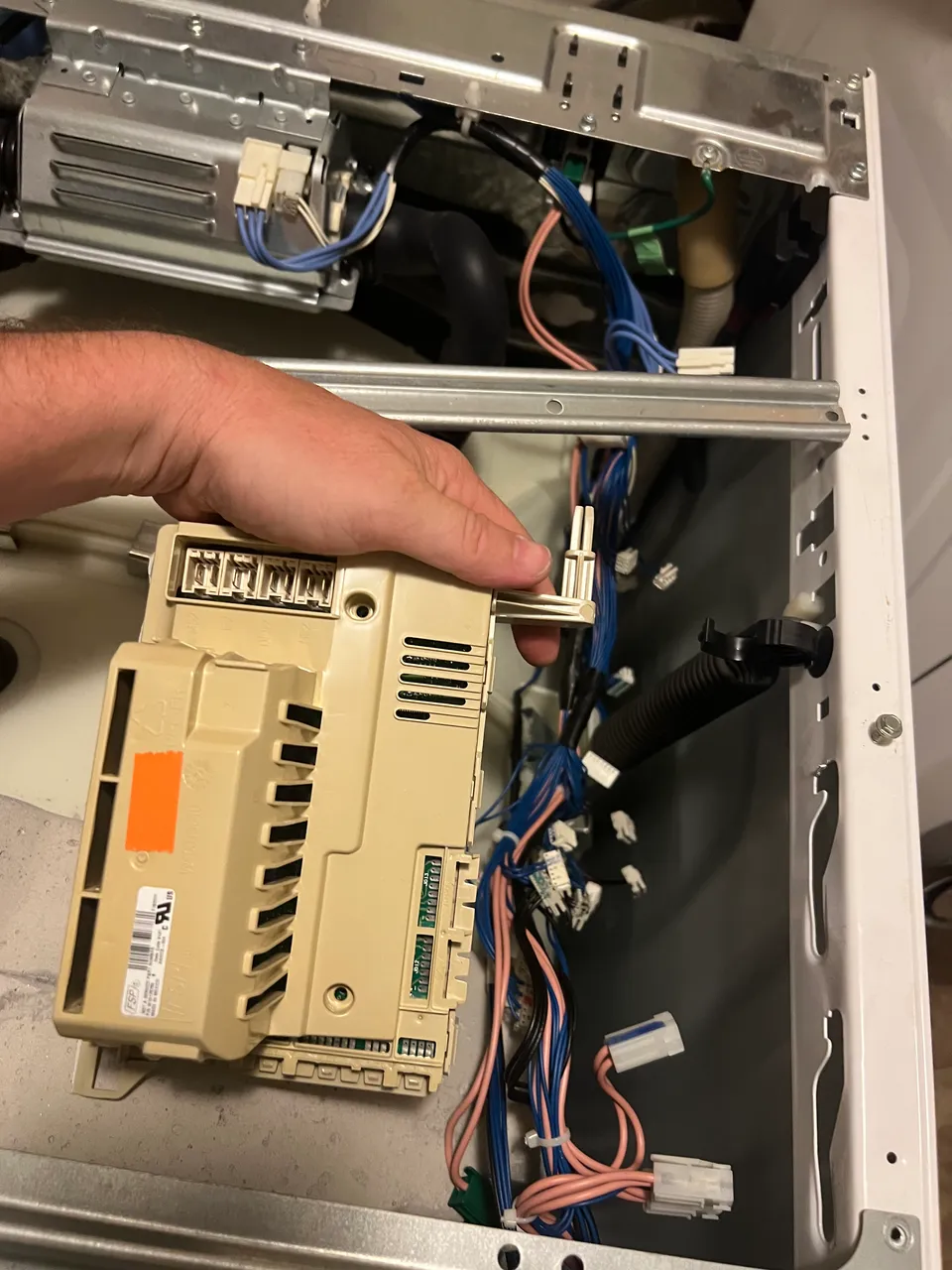
Once that dumb crap was gone I was able to disconnect the 10-15 connectors from the board. Then it was easy to find out that the plastic housing slides to the left to be removed.
I took the assembly down to my super fancy work shop for the final tear down:
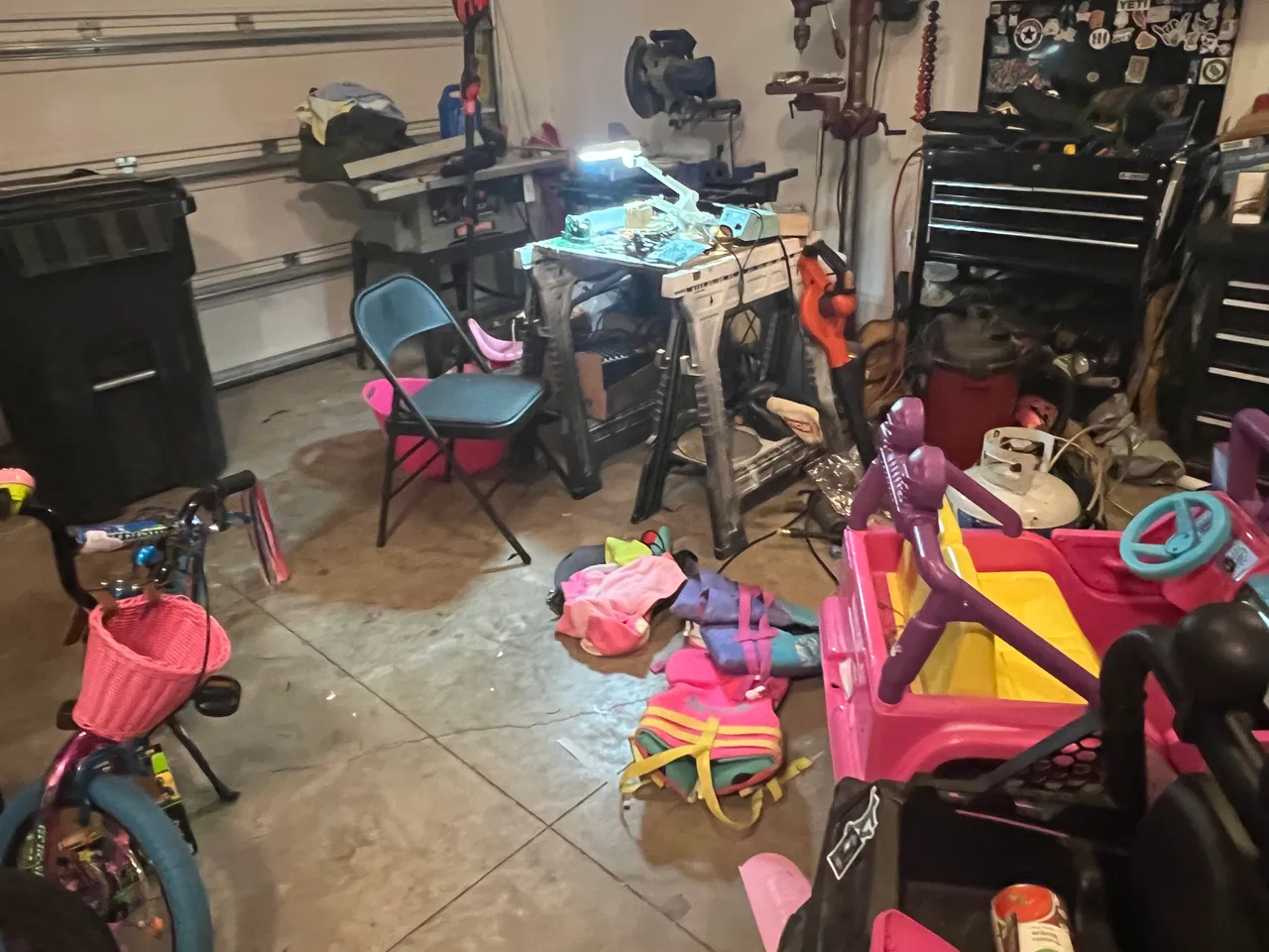
My “work bench” is a little crowded with shit from previous project, but thats not gonna stop me…so no point in cleaning it.

Pretty much I looked for retaining clips and shoved small flathead screwdrivers in whereever I found one. Pretty much just did that and jimmied the pieces hntil something popped and it came apart. Not graceful, but not ineffectual either.

After some screwing with it, it opened up like an alligator mouth. The bottom part was still fighting me, but at this point I knew I was gonna dominate this bitch. Basically here I just ripped it open…but maybe with a little finesse.

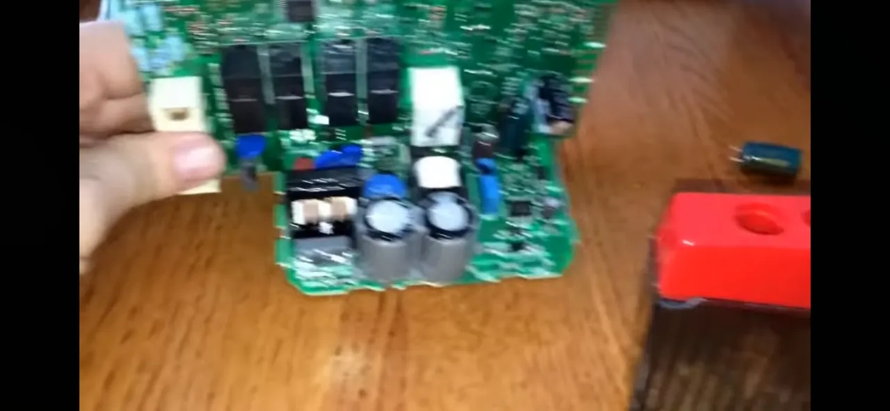
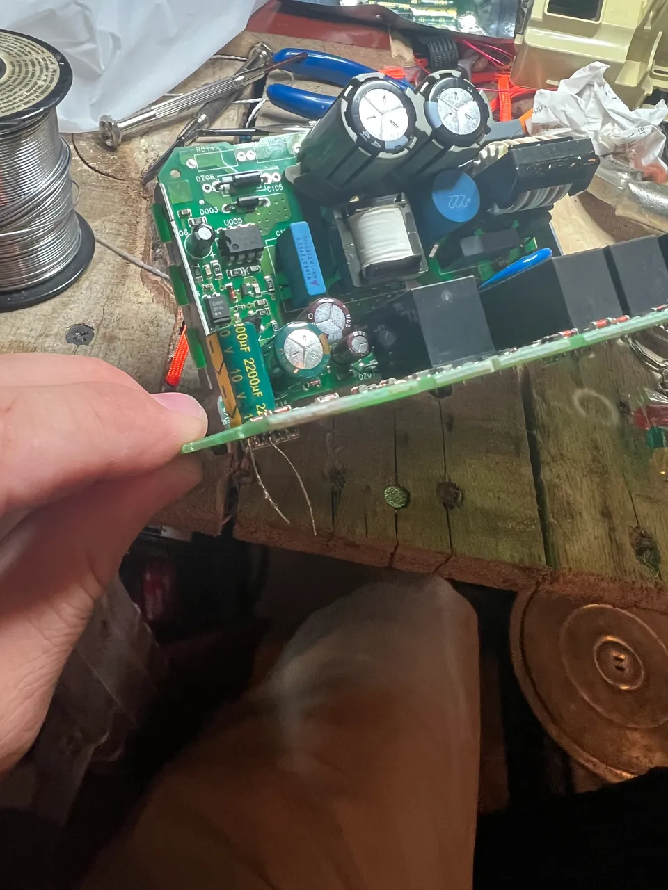
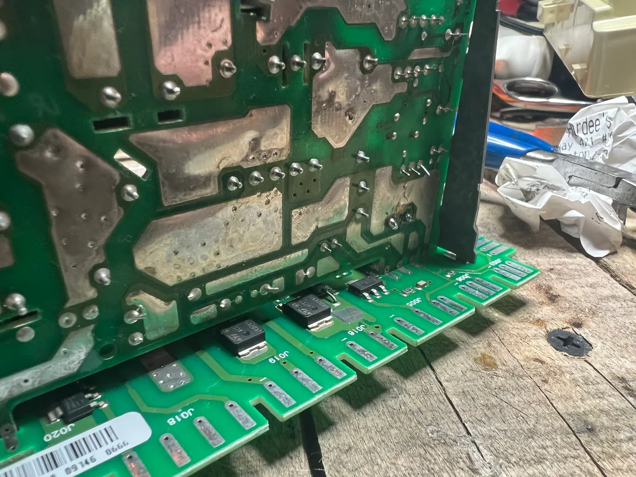
BOOM. Open. And instantly I see several capacitors: and teo of them are 2200uF, and both of them are bad. If you’re nee to this, you can definitely tell a bad electrolytic capacitor when the top is bowed up/convex. Exciting stuff.

I couldn’t find my solder wick, so I had to walk the legs put a little bot at a time. I tried heating both simultaneously, but the conformal coating made it difficult to get the solder workable. As much as it sucked walking these short legs out one at a time, doing the process in reverse to install the new caps would certainly suck more…but thats what I get for losing my wick I guess.


Nonetheless, I ain’t no doggone quitter, so in the shot below you can see those daddy long-legs hangin’ out…the first cap was replaced. Now i just needed to trim the leads and do the other guy.
Here’re the teo little trouble makers, side by side. Birds of a feather, huh?

The second one was much harder. I tend to put the hard stuff off for last I guess…not my strong suit.

Still, as tight as that space was and as pain-in-the-ass as it was, I stuck it out like a grumpy old bastard and got ‘er done. Reflow, trim, yadda yadda yadda, done.

I put the PCB assembly back in its crappy little housing, and prepared to test my work.
Slide it back into its spot…

Reinstalling all these little connectors looks like a mess, but theyre all keyed uniquly, so it was actually pretty straight forward.

Now I needed to replace the “easy” board that I removed first.
This one had two connectors thay were almost keyed the same. One could fit in either position, the other could only fit in its position. Kinda like .556 and .223…@galenkp knows what I’m talkin’ about.
Took me a minute of struggling before I finally just pooped the housing back out to get a better look; after that it was easy enough to get things in the right spots.

Now that all the crap was back in, I ran a quick test. Once I saw rhat it worked (and it was good lol), i powered it doen and swapped the old pressure sensor back in. Test agin before closing, and wouldnt you know it, one of the two faults (SUD) came back. Damn. I was really hoping to return that sensor and get my ninety bucks back. Oh well, c’est la vie or whstever.

Inout the new sensor board back in, prayed that the old sensor board hadn’t blown my new caps, and tested ine final time. Thank goodness, I thought…it worked.
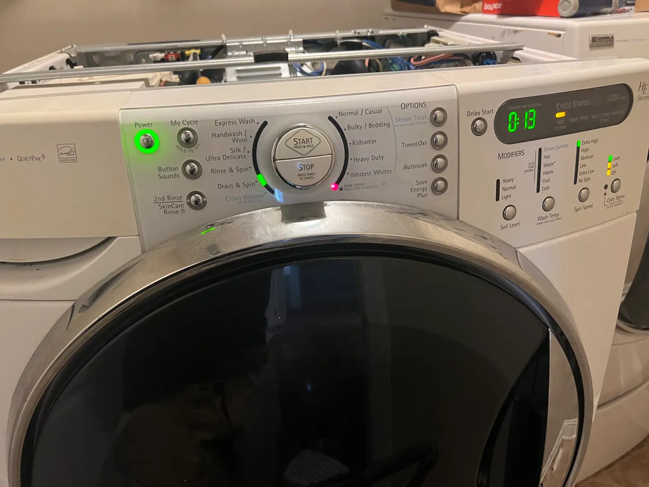
At that point, I reinstalled all the oretty covers and junk, pushed the heavy bastard back into its normal spot, and got started on a load of much needed undies.
So if you have a Kenmore washer and you start seeing F35 and SUD errors together, and youre a cheapo like me, hopefully this will help save you some trouble.

If you enjoy my content, check out the Albus Index!
Here you’ll find links to various post-groupings, so you can find all posts related to a specific topic quickly. Topics include lists of brewing recipes, flutes, crypto talks, rucking posts and an index of all acoustic covers. The lists are updated as new content is added, so they can always be used to quickly navigate my content.

source