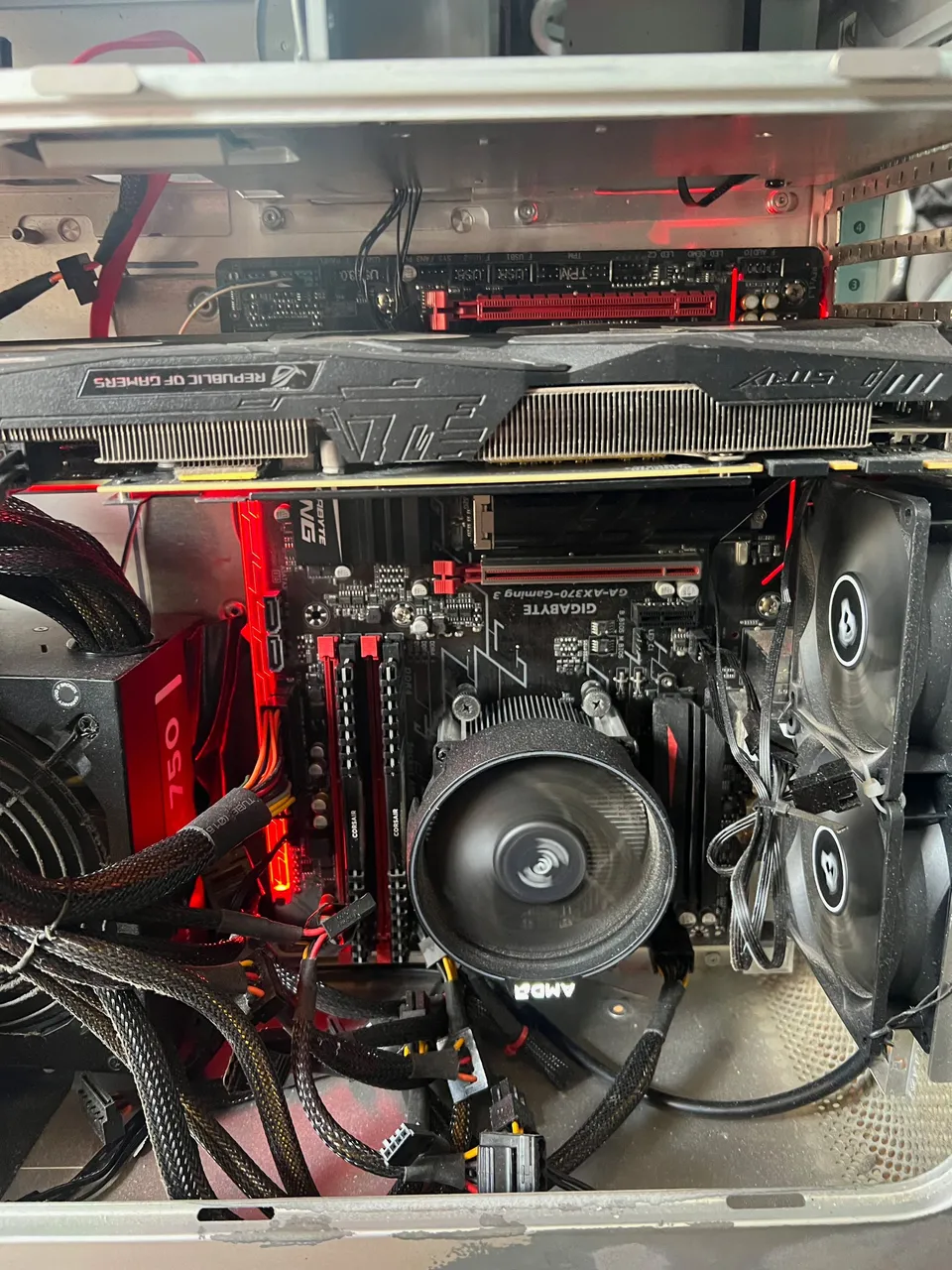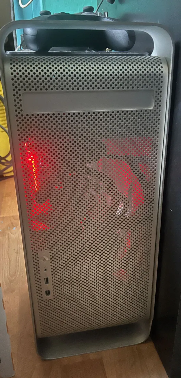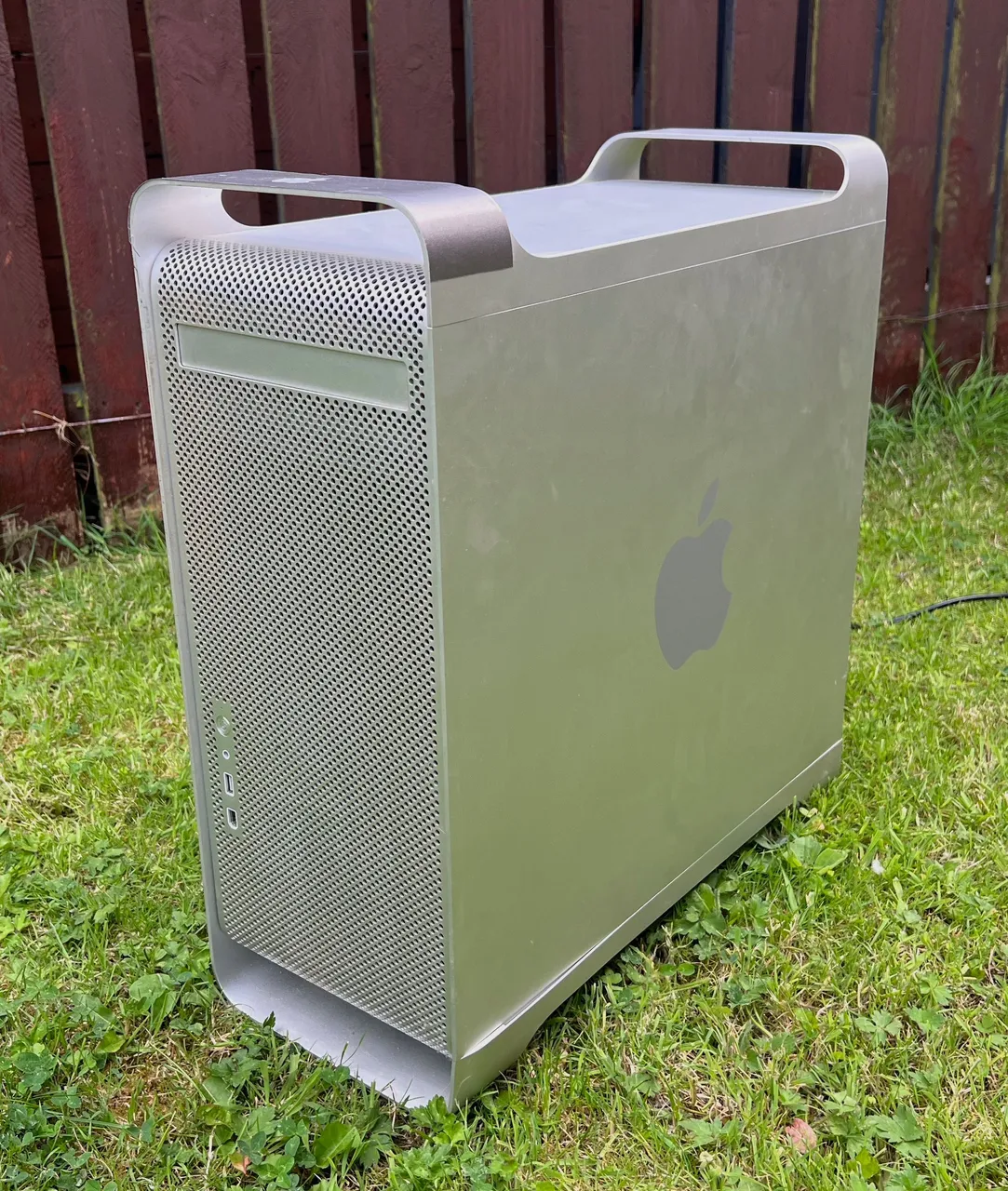
This is hands down my craziest pc build idea ever, especially because it never even existed as a potential project - it just happened.
While putting together my previous posts on the budget office pc build from used parts see
@c0ff33a/the-mysterious-and-complicated-tale-about-building-a-computer-from-used-parts
@c0ff33a/the-mysterious-and-complicated-tale-about-building-a-computer-from-used-parts-part-deux
I had to look up reference pre-built systems of similar specs to confirm putting together random parts could be more cost effective then buying something fully built used - randomly on one of my searches one of the eBay listings that popped up was a Mac Pro Cheesegrater tower.
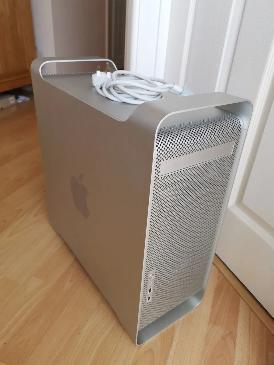
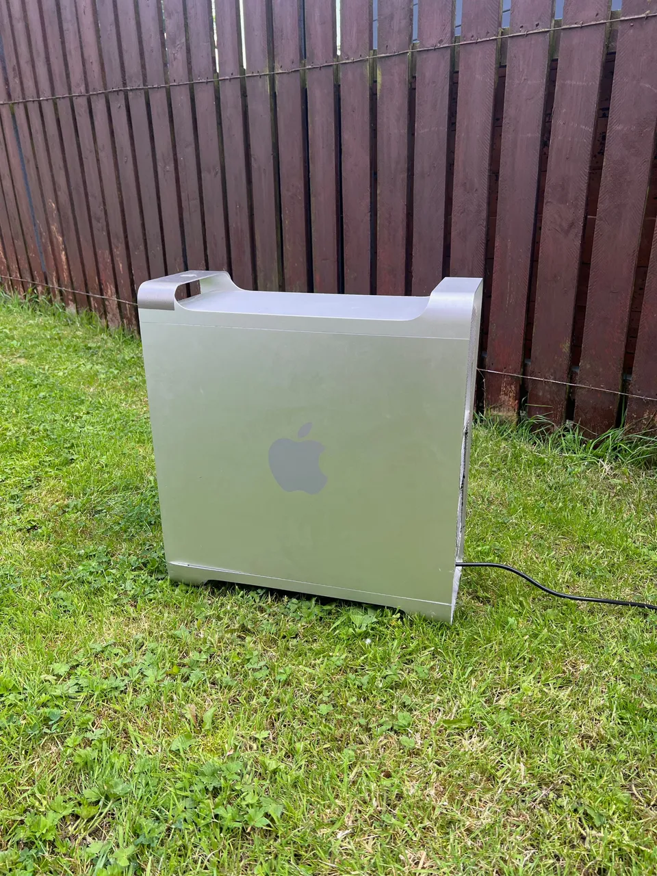
It was listed as dead, spares and repair - but really the components inside were of no interest compared to the case itself. Aside from being a big Apple fan, with a ridiculous amount of hardware from them including the MacBook Pro I am typing this on, the trashcan Mac Pro I use at work, MacBook Air, iPhone 13 Pro Max and numerous iPads and a couple of Mac Mini’s - the cheesgrater Mac Pro was the last piece of legacy Apple hardware I did not have in my collection.
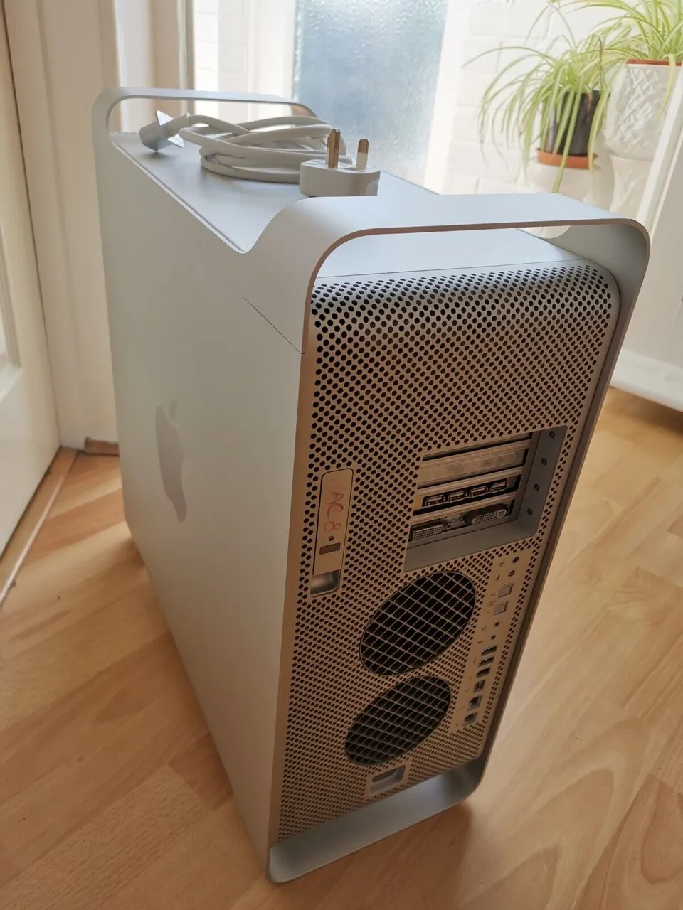
The price was fair as it looked in mint condition for a case 15 years plus old, it was collection only but I managed to persuade the seller to box it up for carrier collection as it was located on the South Coast of the UK some 8 hours round trip drive.
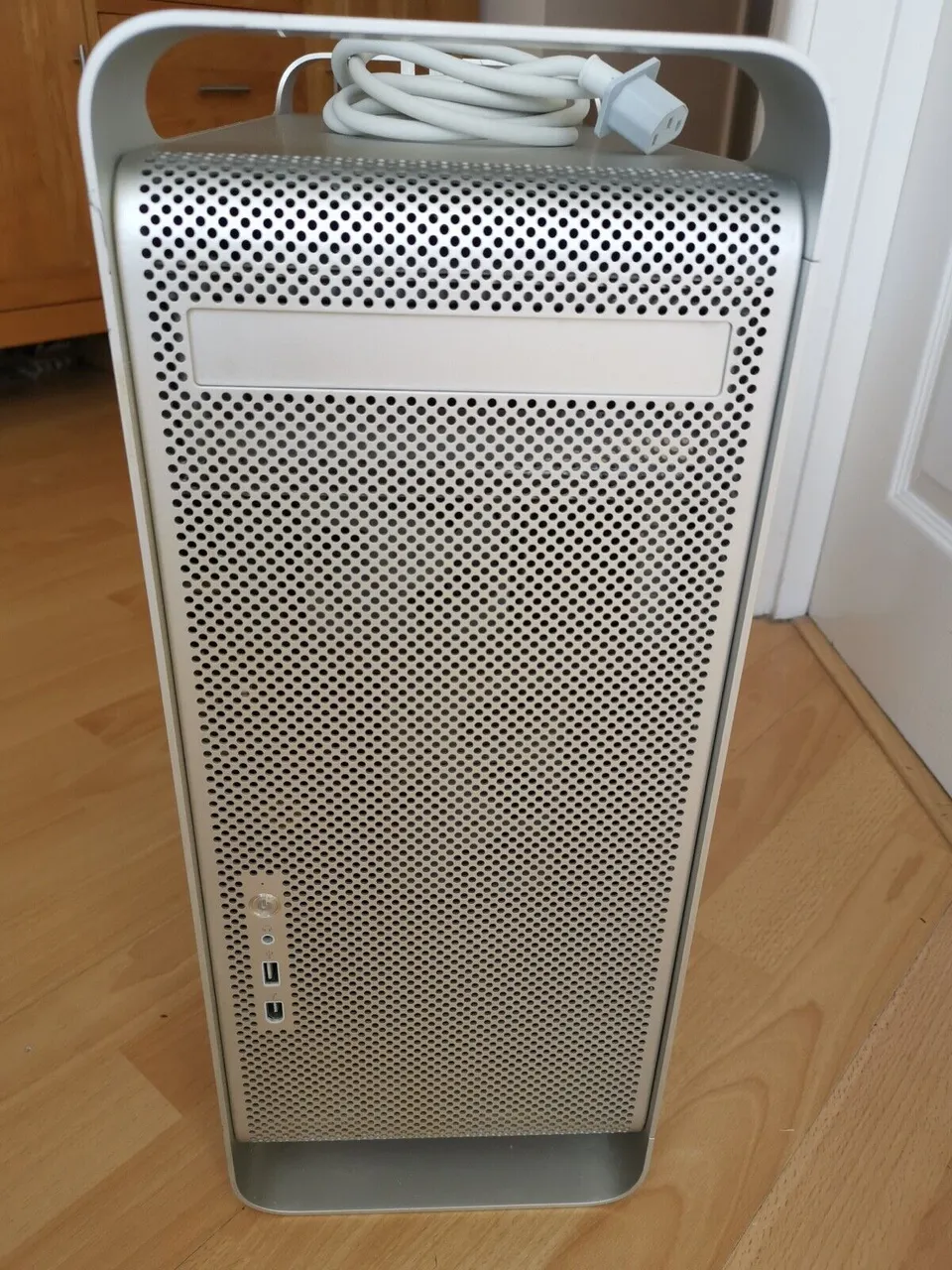
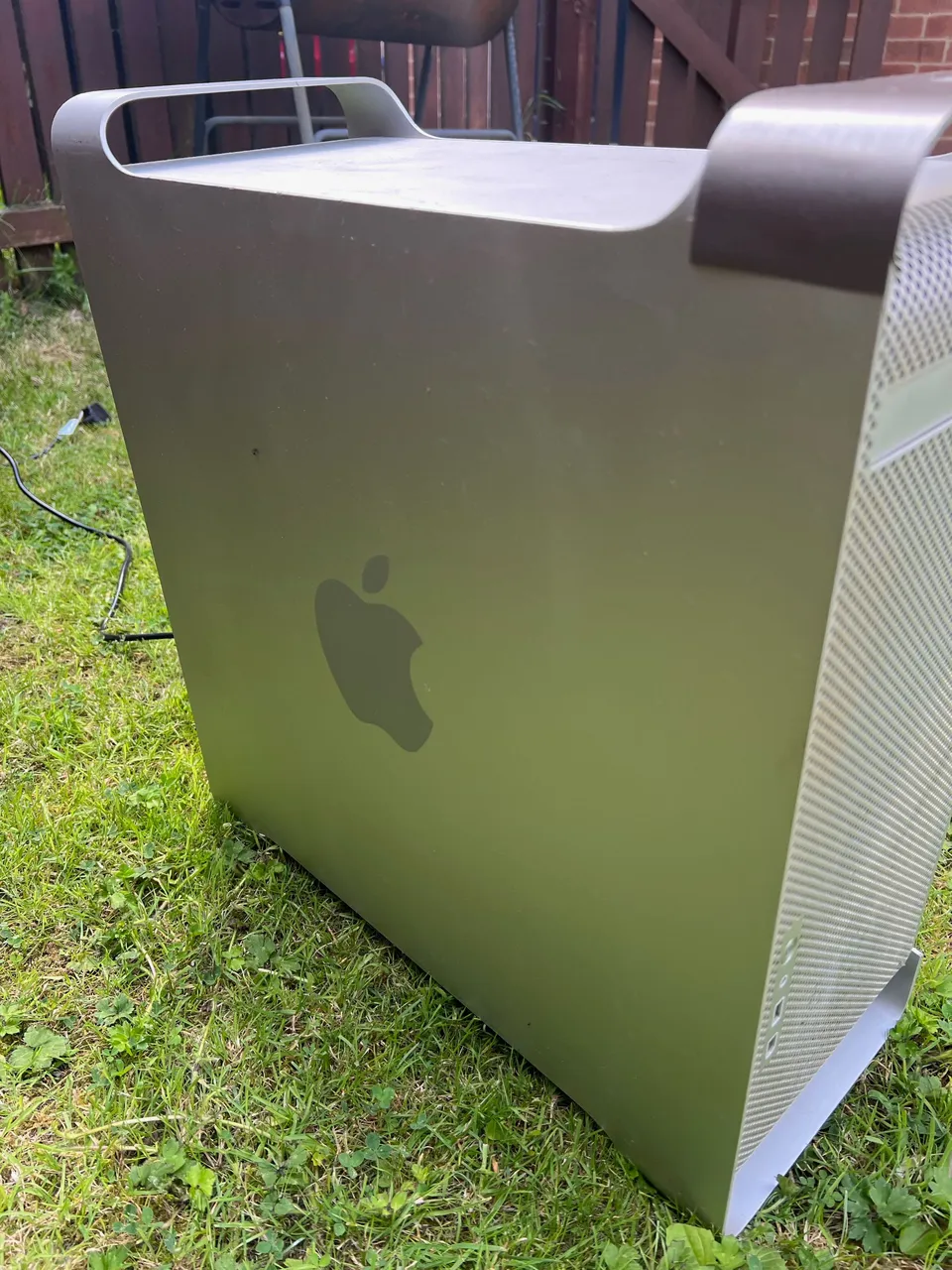
So I bought it with no idea what I would do with a non working Mac Pro, and when it arrived it was definitely not working - most likely dead PSU. It was also the first generation of the Mac Pro’s - a 2005 PowerMac G5. It had two 80gb original 3.5” spinning hard drives in it - surprisingly both still worked when plugged into a USB enclosure to my MacBook Pro - the boot drive had a clean install with files dates of Mid 2010 - but never used just a set up install. Inside it was super clean like the outside - hardly any dust or dirt - this system must have had hardly any use in its….18 years of existence!
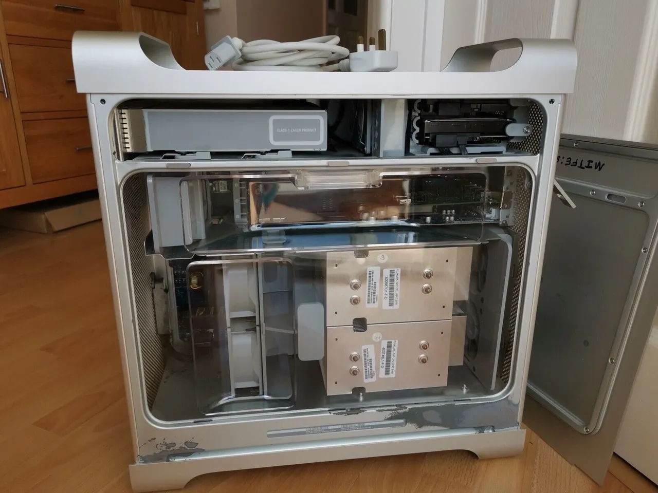
What to do with a very solid aluminium tower case when the internal components are both very aged and totally not working. I could of course have maybe found a replacement power supply and got it running - but really however good Apple hardware is at 18 years old this would be a pretty horrible slow experience. Maybe a table base, or just strip it out and use it as a storage cabinet that looks pretty.
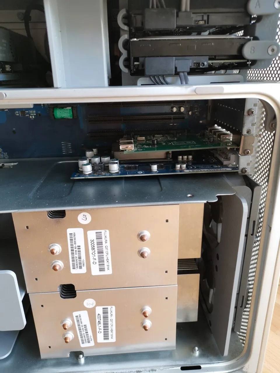
The answer however was hiding in plain site, strip the old components out and cram in a gaming pc build. The reason for me is at home where I sit on the evenings using the MacBook Pro is a high traffic area of the house. I use an iPad on an stand for streaming video content - but it’s on the way out the charger connection is very fickle and the battery is toast so half the time it’s dead until I find the perfect position to plug the charger in.
Switch that to a gaming pc with wall mounted gaming monitor - reliable streaming content and gaming when I fancy. But being in a high traffic area at home - people and stuff dragged past daily a standard pc case would be smashed in no time. Most modern gaming pc cases are all plastics aside from a tempered glass side panel, with air flow a priority the top is all air flow mesh grill, same for front and back. The tops especially are just begging for accidental spills to fry your motherboard and graphics card. Compare that to this PowerMac G5 case - solid aluminium top, bottom and sides, front and back aluminium mesh so solid you can hit a hammer on the front mesh and it won’t do a thing! Apple manufactured these cases to be bomb proof - perfect to sit in an area where your family are going to be back and forth with stuff all day every day.
Now modding these Powermac G5 / Mac Pro Cheese Grater cases is not new, in fact it is so popular the odd business has popped up to sell specific hardware to make to easy. The reason they are needed is nothing in the case confirms to modern pc hardware - motherboards be it ATX, Mini ATX or Micro ATX just don’t fit - same for power supply, Apple used a custom supply long and thin that sat at the base - the nearest similar would be a server PSU. So fitting a modern motherboard inside needs a lot of work, and of course I have a spare PSU so no need to buy one - but fitting that in needs planning. Worse still the back IO plate matches nothing, and the front IO and power button again is Apple proprietary so no way to easily connect to a pc motherboard.
If money is no object most of these problems can be easily fixed, you can buy a custom cut motherboard tray that fits the existing stand offs in the PowerMac G5 case, and a custom cable loom that plugs into the front IO socket providing the cables needed to connect to a modern motherboard. You still need to Dremel out some of the back plate to give the io and power supply access but it would end up being a pristine conversion - showcase like even.
But as I never even planned on doing this, it’s definitely going to be another budget build - so these custom parts would pretty much cost as much as a Motherboard and CPU on their own. My plan instead is to angle grind the motherboard tray from a donor old PC case and rewire the front IO cables from it to the Apple front IO. Fitting the donor motherboard tray has a few options - from using the existing stand offs and drilling new holes in the tray to use them - or removing them totally and epoxy welding the tray to the back wall of the case. (For reference, unlike a standard pc case this Apple case has a solid fixed side panel, and an opening access side panel. On a normal PC you can remove both sides, and the motherboard mounts to a second panel that sits just offset from the right hand side removable panel)
With a plan formulating nothing can happen until I have the hardware to put in, so I now have to source a suitable motherboard. My aim is to replicate my boys first pc build in 2017, so I look up best gaming motherboards of 2017 to then source them used on eBay. This proves to be harder than I expected, pretty much all are not even available used - Motherboards are quite reliable so finding used versions is really hard because if they are working people still use them. I eventually found this listing
https://www.ebay.com/itm/155323473549
GIGABYTE GA-AX370-Gaming Socket AM4 DDR4 ATX Motherboard
Highly praised at the time, has a m2 pcie SSD slot, really good price but has a faulty PCIe x 16 slot - but it has two and I only need one for the graphics card so worth the risk.
With the Motherboard selected now it is just a matter of selecting a matching CPU and Ram for it - returning to my reference 2017 gaming pc build guides this comes up top for CPU
https://www.ebay.com/itm/285102514086
Amd Ryzen 7 1700 cpu great price and includes stock cooler as well.
Ram was more tricky, after choosing the CPU I tried to narrow it down by looking what worked best with the CPU. 16GB is enough for gaming, but looking through the options this came up
https://www.ebay.com/itm/185752561603
Corsair Vengeance LPX 32GB (2x16GB) 3200MHz DDR4 Memory
Perfect for the processor, and for the price having 32gb gives extra options for the build including running virtual machines
Finally as this is going to be a gaming build it needs a reasonable graphics card, knowing the GTX1070 in my boys old build works fine for all titles I like to play this was the aim - I managed to find this listing
https://www.ebay.com/itm/185748009954
The price was reasonable, I could have held out on auctions but generally any I had looked at would end at more than this anyway.
One reference note for eBay - I use it a great deal to source things I need, and it is really a great way to “recycle’ products. But it is also a massive gamble, scams are widely reported with either cheap replicas shipped, basically boxes of ripped up card just so the tracking shows received etc. I can honestly say I have never had a problem buying on eBay - but I do my due diligence. First - if it is too good to be true - it’s a scam. If something is far cheaper then anyone else is listing - it’s most likely a scam. Second is seller feedback
https://www.ebay.com/usr/codeandchips?_trksid=p2047675.l2559
You can see here the graphics card seller has 100% good feedback, they might have only sold 32 items but have been on eBay since 2008 - so there is good history. This adds confidence to the purchase.
Sellers with zero or only a few feedback, with accounts a few months or less old - I really avoid and they are nearly always the ones with the “too good to be true” pricing.
That said eBay has really good seller protection, so if there is an issue you can often quickly get a refund if the seller failed to deliver - but really who needs the hassle? If you are going to buy on eBay buy wise - check out the prices in general of what you are buying and look for a good price in the range - and for a seller with good feedback that has been around a while.
Now the fun part, wait for the parts to arrive, first is the Motherboard which was very well packaged in a solid specific plain box, with anti static bag for the motherboard itself and io plate taped to it (not that I would need it for this build)
Second Ram, from a commercial reseller it was really well packaged and arrived in two days.
Third the CPU, the seller reused a box from a different AMD cpu which gave me a moment of worry as it was a lower spec Ryzen 5 box - but the CPU was the listed Ryzen 7 and unlike my previous budget build at least this CPU had been safely packaged in it’s factory holder, along with the factory cooler - so all safe and sound.
Four the graphics card a couple of days later, very well packaged and super clean for a used card - very pleased. The seller actually got in touch a day later because his tracking showed it was not moving at the hub of the carrier - so he was worried it was not going to arrive. I was more than happy to reassure him it had arrived and left positive feedback - I sell myself obviously and these things happen to me as well so I appreciated him chasing up.
Because this build is totally non standard, I needed to check the whole system boots and runs prior to trying to cram it into the Apple Powermac G5 case. So basically the bare motherboard needed test-benching outside a case - in this case using a cardboard layer on a desk to avoid static. (reference note I was caught up in the idea of building this, I totally forgot to take any photos of the case as it was taken apart, or the motherboard in test bench state - so all the photos are basically before starting and after the completed build)
Fitting the CPU seemed to go well, I did have to google some videos of the board and cpu install - there is a triangle on the cpu corner and on the motherboard fitting that tells you where to match the CPU so it fits the board correctly - I could see the triangle on CPU but not the motherboard fitting - so watching videos I could see how the CPU text was orientated to point me in the correct direction. Lift the lever, press the CPU lightly into place and close the lever.
First big problem on this build, fitting the CPU cooler I realised it needed a back tray to connect to that is normally shipped with the motherboard. Obviously my used motherboard did not include this - and without it there is no way to mount the CPU cooler.
https://www.amazon.co.uk/dp/B087M1ZRPJ?psc=1&ref=ppx_yo2ov_dt_b_product_details
Amazon to the rescue with prime next day delivery - an extra £7 on the build but if the Motherboard is good it would still be a bargain even adding that on.
So when that arrived I could mount the CPU cooler with a good pea sized blob of Artic Silver thermal paste, clip in the ram, fit the existing 512gb M2 pcie ssd and hook up the existing 750watt Corsair PSU 24 pin main power connector and 4 pin CPU connector.
Everything connected, time to power up the test bench - I found a good priced old 24” display to wall mount
https://www.ebay.com/itm/134413418626
And this would be my test display, for first testing I decided not to fit the graphics cards and use the onboard motherboard HDMI port.
To start a pc with no power button (because no case with it on!) you can use an electrical testing screwdriver to briefly connect the two pins on the IO pin out that are marked for power on. So with the PSU plugged in and connected - all the parts connected on the motherboard, I jumped the two pins with the screwdriver and……nothing. No lights, no fans - nothing basically totally dead.
Next step reseat the power connectors from the PSU nothing. Try a different PSU nothing. Switch ram positions nothing. Try only one ram stick in all four slots - nothing. Starting to think the motherboard is DOA, google motherboard spec for boot issues - many suggestions to clear cmos by disconnecting all power, removing the cmos battery for a few minutes and then refitting - end result still nothing.
So now I am really stuck, the motherboard has zero signs of life and even on the previous budget office pc build there were fans and motherboard lights even if it did not post. The last thing to try would be reseating the CPU - so I carefully unscrewed the mounting screws in the correct order - lifted up the cooler with no effort - and looked underneath to see the CPU sat stuck to it! This can happen with baked in thermal paste if you pull up really hard - but with fresh paste and no effort - the cpu was obviously never even locked into the slot in the first place - hence my issue.
Carefully twisting the CPU from the cooler I checked the pins to make sure my unexpected extraction had not bent any - fortunately it was all intact. Second attempt at install - I pressed down far more firmer and there was an audible thud as it fitted down. I must has just had it sat on top of the locking mechanism rather then fully in place.
CPU installed for the second time, heat sink fitted and try to jump the power pins - result! Lights and fans on the motherboard. Such a relief - but quickly dashed no video post at all. Checking the motherboard diagnostic lights there is an amber VGA light - look that up and it turns out while the motherboard has onboard graphics out via hdmi and vga - not all cpu’s can use them - and guess what - my cpu has no onboard discrete graphics.
So now to fit the GTX 1070 GPU so I can finally post, but I know the motherboard has a PCIE slot issue but not which one - out of the two I choose the furthest from the CPU - the theory is generally the slot nearest the CPU is the fastest - so that is the one everyone would use and could get damaged during removal and refitting. GPU fitted, HDMI connected to it and of course Gpu power and we have post! Bios screen pops up were all are all good.
Finally getting somewhere it is time to plug in a Windows 11 install usb, keyboard and mouse - boot to the Windows 11 installer, of course my system is not currently suitable for Windows 11 so back to the usual installer registry hack to bypass the installer checks and install Windows 11.
Booted into Windows 11 it all looks good, and another pleasant surprise yet again this used Motherboard is already activated for Windows 11 - so two used motherboards and both have a fully licensed Windows 11 bundled with them. This is a really big benefit of Windows licensing being tied to the motherboard rather then a key, the days of either paying for a licence or using some scetchy key bypass that no doubt totally compromised your whole pc with rootkits and key loggers are long gone.
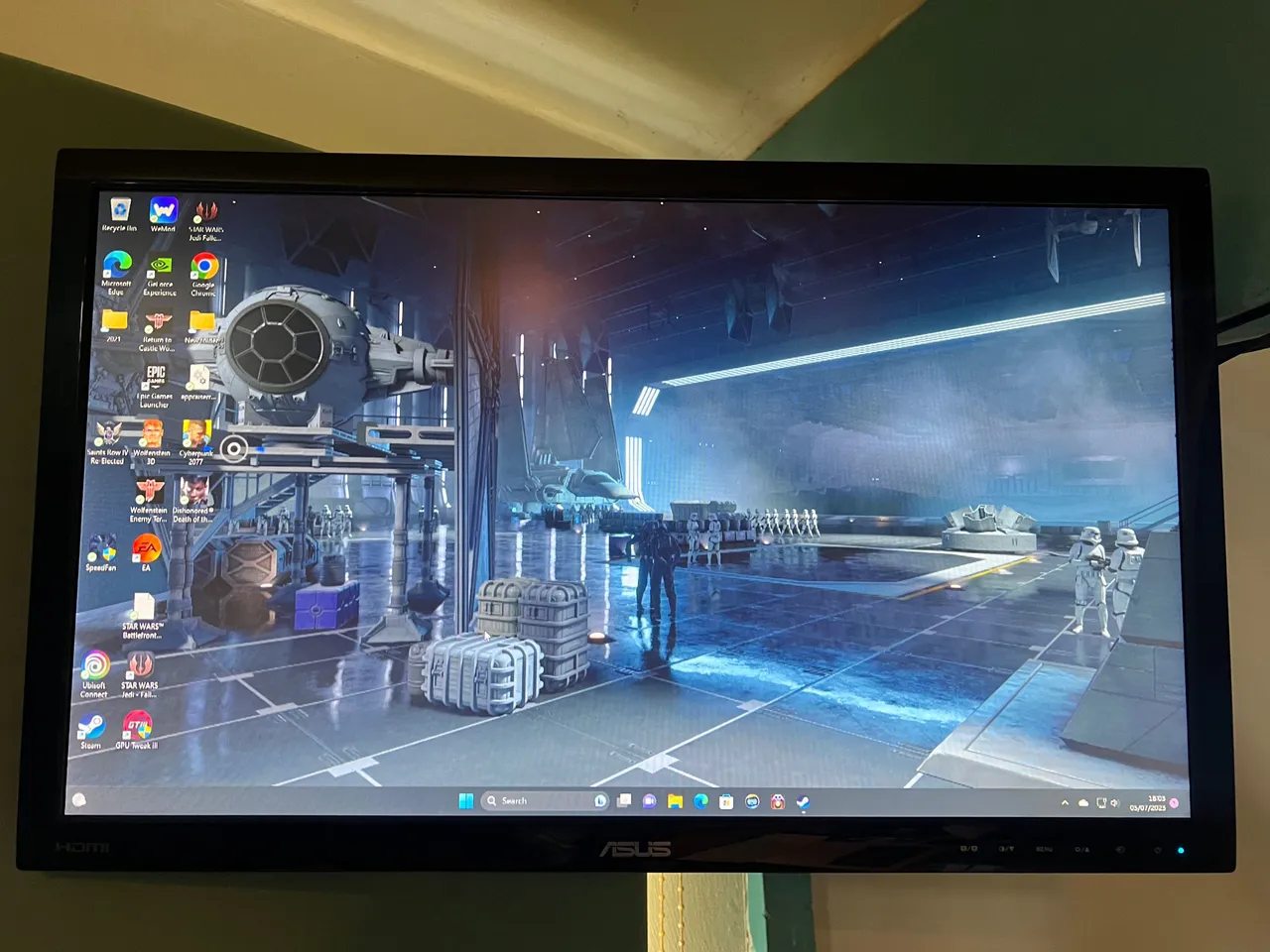
Windows 11 with live video wallpaper from Wallpaper Engine
With Windows 11 running smooth, I set up Splashtop Remote Desktop so I could test stability while at home and set up Steam, Epic and Ubisoft to get some games installed. But 512gb on the NVME is quickly going to run out, so for extra storage an 1tb SSD is going to be needed.
https://www.amazon.co.uk/dp/B078211KBB?psc=1&ref=ppx_yo2ov_dt_b_product_details
Back to Amazon for reasonable price and quick delivery.
Hooking up the SSD on the test bench set up should have been easy as all the SATA ports on the motherboard were easily accessible - but it turns out you can’t account for the stupidity age sometimes likes to slap you with. Power and Sata Cable plugged in the SSD refused to show up in Windows, I tried all the different Sata ports just in case maybe the NVME was using one of the lanes from a Sata port causing a conflict, tried different Sata cables still nothing. Finally I thought maybe the power cable was defective from the PSU - it was when I unplugged the power I realised my idiotic mistake. From previous motherboard troubleshooting I had used a second power supply just to check the issues were not PSU related - it was still sat next to the test bench and some how I plugged in the power supply from the unused PSU into the SSD. So yes it had a power cable plugged into the the SSD - but the power supply it was connected to was not even plugged in - and even if it was as the motherboard was not connected to the 24 pin connector it would not provide power anyway. I made a mental note to put away test items when finished with, plugged in the working power supply connector and the SSD was instantly recognised so it could be formatted.
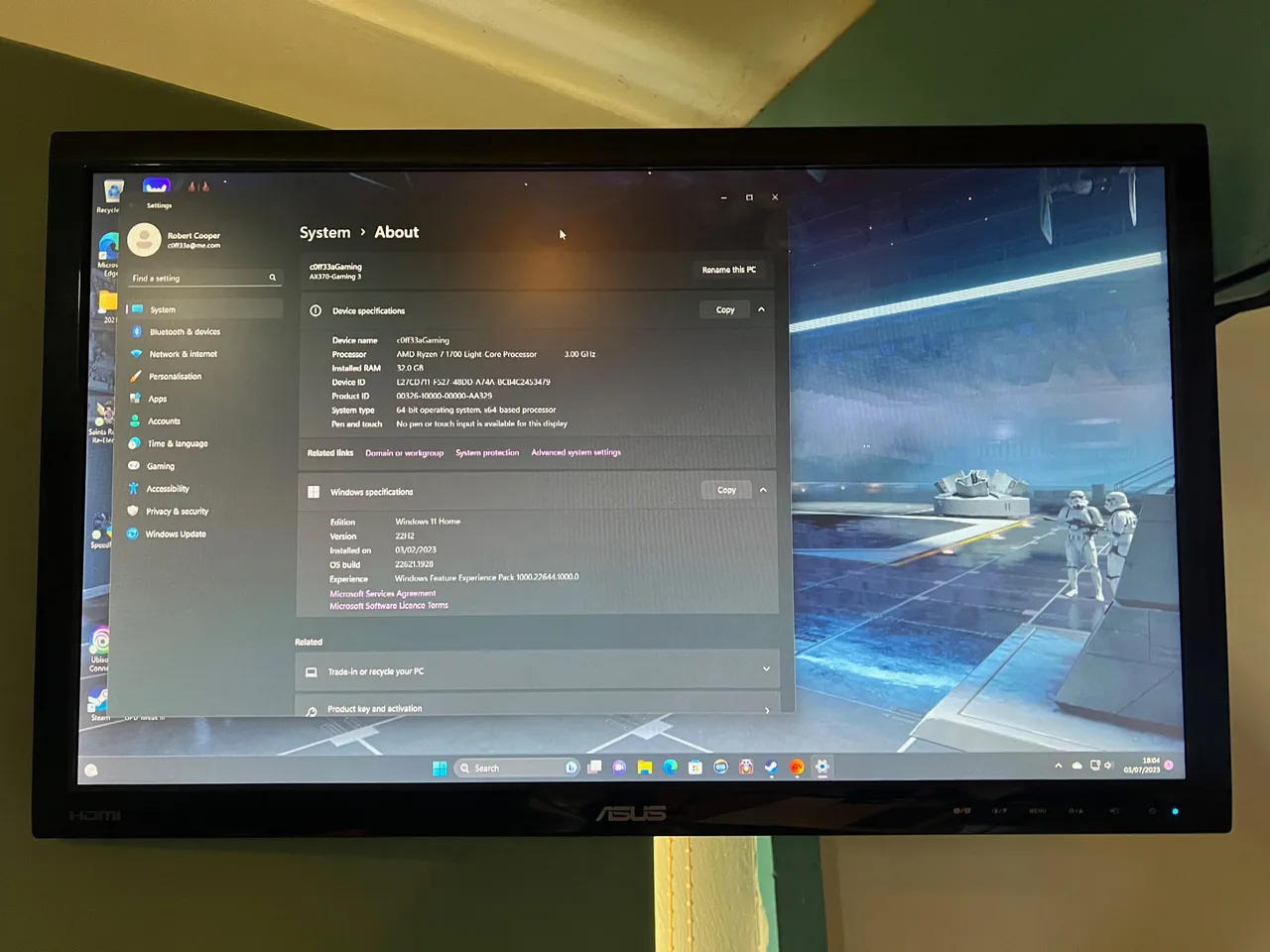
Windows 11 Specs
Finally it is time to look at the Powermac G5 case, fully stripped out of the original Apple hardware - what remains is a challenge to fit a PC ATX case into a housing that is not designed to support it. There have been many different methods tried to achieve this, you can purchase a motherboard tray custom cut to fit the existing motherboard pin out points in the G5 case - they are however quite expensive. Others have used a donor pc case - cutting out the motherboard tray and fitting it into the G5 case. As I have quite a few old defunct pc cases hanging around the latter was the obvious route - but how to fix it onto the case? Using the existing motherboard mounts would need precise holes drilling in the donor tray - and that would be nearly impossible to achieve without specialist tools. Those existing mounts are just basically welded to the the back plate, will literally knock off with a hammer tap. So my plan turned into knocking those off, and using a metal epoxy to fix the motherboard tray to the aluminium back plate of the Powermac G5 case.
https://www.amazon.co.uk/dp/B009EU5ZMA?psc=1&ref=ppx_yo2ov_dt_b_product_details
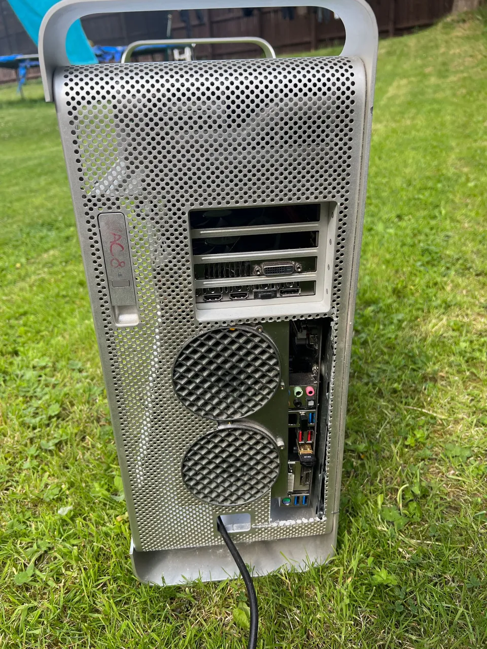
Key to this plan is making sure the motherboard matches to the back of the case, and the most important would be having the GPU fit into the existing case PCIE outlet ports so it could screw in solid to the existing fittings. To achieve this proved tricky, basically fit the motherboard with GPU fitted into the case so the GPU hooked onto the existing PCIE brackets. As the back plate in no way matched my ATX motherboard IO connections, the aluminium back plate needed removing - achieved by using an angle grinder to cut out a hole just big enough to give access. With the GPU and motherboard fitted in the expected place on the inside, I could see through the back grill holes of the aluminium back piece enough to marker off the area I would need to cut - and then take it all out and start grinding!
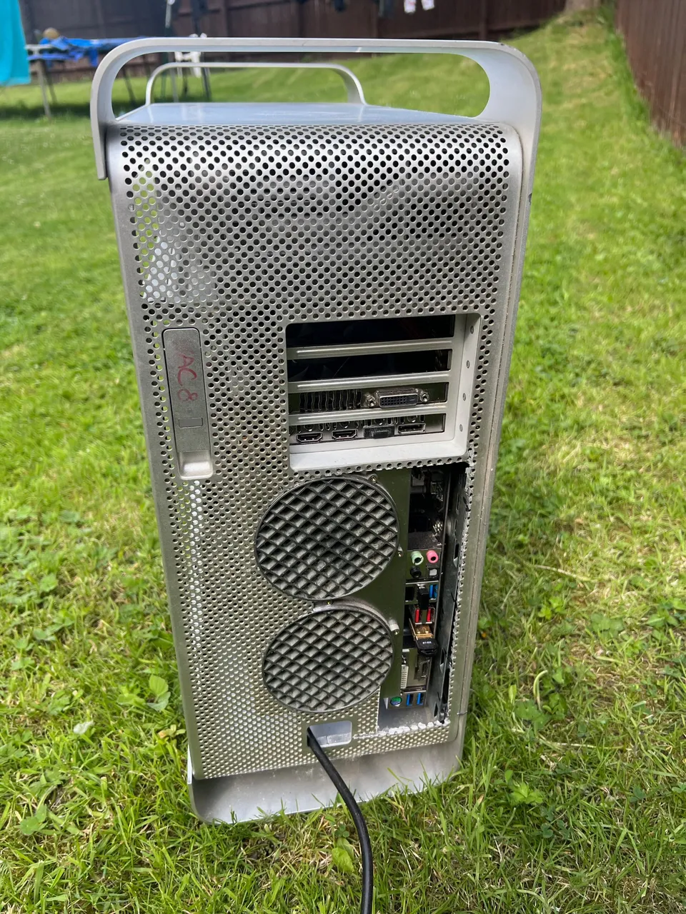
Generally cutting went well, most people trying this use a Dremel for precision - not a full size angle grinder. But nobody looks at the back of a PC case, especially not where I would be using it - and this is no showcase build so a touch of over run on the cut did not concern me.
Another pre test fitting of the motherboard in the case and my cutting was spot on - all ports accessible. Now to fit the motherboard to the donor tray, fit that back in again mounting the GPU to the case PCIE mounts - and mark off on the motherboard tray and Powermac G5 case reference points of where the tray needs to be so it all sits nicely together.
Finally remove the donor motherboard tray from the motherboard, mix the Epoxy resin and apply it to the points on the donor motherboard tray that will touch the Powermac G5 aluminium back wall. Now fit in place the motherboard tray, taking care to match my alignment pen marks on the tray and case, add some weight on the tray to keep it pressed against the back wall of the case, and use the left over epoxy I mixed to fill in various edges between the case and motherboard tray for extra solidity.
Once the epoxy has set I tested the hold by pulling on the motherboard tray and pushing on it in various place - it seemed solid but I was not putting excessive force on it - in theory at least having the GPU locked into the PCIE slot would keep everything in place anyway - it is by far the heaviest component and screwed into the case would provide support. But if I was out even a fraction when epoxy welding in the tray - the GPU would not line up with the screw mounts on the case and that would be a big problem.
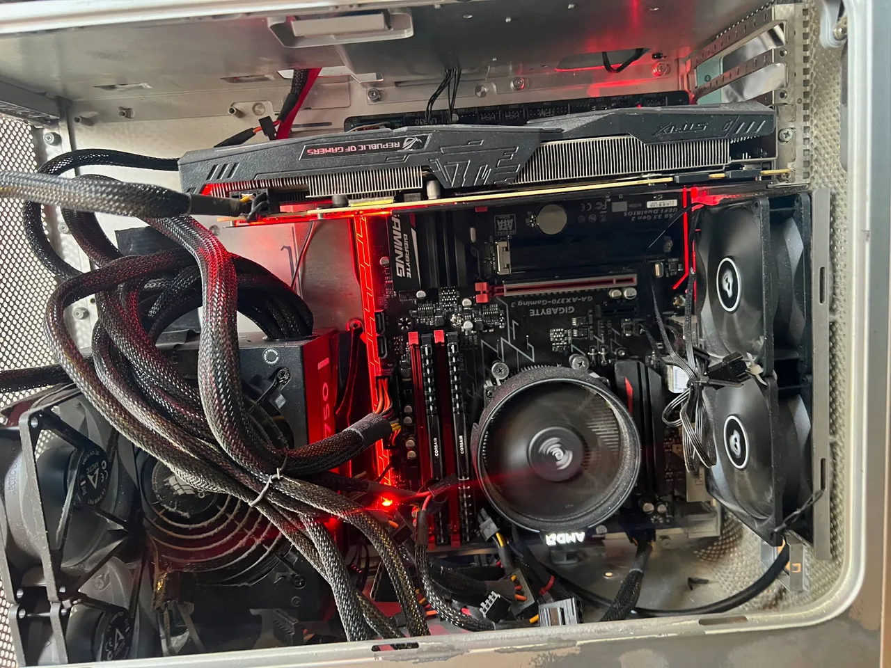
Anyone that has built a pc before will notice the motherboard is upside down compared to standard PC cases - that is the PCIE slots are at the top rather then the bottom. That is because as you look at a normal pc case front on the left side opens, but on the PowerMac G5 it's the right side that opens. It all works well though as the PCIE openings on the case are at the top.
The motherboard mounted fine, and all IO on the back as expected was clearly visible - although the motherboard had its IO shield this was not going to fit, and really not important nowadays anyway. Fitting the GPU did take some finesse - it was tight for sure but after a few goes it clicked into the mounts and screws added to lock it into the case - big sigh of relief hardest job done.
The Powermac G5 case does have front IO - power on button, USB 2 port, Firewire Port and front Audio port. It uses a specialist cable to connect it to the Apple motherboard. You can again buy a specialist conversion cable that plugs into the front IO port and then gives you all the leads to connect it to a ATX PC motherboard - but again it’s really expensive so I went with the cut existing cable and solder your needed cables to it. The cables I had from my Donor case the motherboard tray had been angle grinded out of, and using pin out guides found online. Two attempts at this, the main thing I wanted was the power on switch to work - first one it did nothing. Double checked and decided I might of misread the pin out and reversed it, second attempt and some how the power switch was basically permanently grounded - so the pc came on then immediately rebooted (as if you were holding the power button in.) Getting very bored of fiddling with tiny wires, I pulled the front IO apart, the power button had tiny wires connecting to the board the cable plugged into - cut them and soldered the two power cables direct to them - that worked press power button PC comes on. No other front IO, which did not bother me I don’t need a slow USB 2 port, have never needed a Firewire port and have no use for front audio - so the power button turns on the pc as expected and everything else on the front is just decoration - fine by me.
At this point the pc is reaching functional motherboard and GPU mounted, the power button turns it on. Next up is to mount the case cooling fans - Apple made this a straight forward wind tunnel - cool air in the front and hot air out the back - it’s totally sealed top, bottom left and right unlike modern pc cases which have top air cooling and often bottom vents too. It is worth noting this is one of the appeals of my build in this ancient case - aside from the bullet proof aluminium construction - any random little accidents with spills (aside from spraying water in the front of back) will not affect it. Given knocking a cup of something from a desk would come from above - knowing where I would be sitting this build it would be pretty safe from most accidents.
Now the original fans were pristine clean and would have been ideal to reuse - except Apple being Apple used proprietary connectors to the motherboard. The pin outs are available but basically the best you can do is connect 12v in and ground to have them run full tilt all the time - which apparently moves tonnes of air through the case - and sounds like a light aircraft taking off. Some hardy modders managed to use a 12v variable resistor to adjust the voltage and thus fan speed - but this needs an accessible twist switch and means you have to manually adjust the speed to your systems needs. So forget that as case fans are cheap and the motherboard can control them as it needs
https://www.amazon.co.uk/gp/product/B097C717Y4/ref=ppx_yo_dt_b_asin_title_o01_s00?ie=UTF8&psc=1
No need for RGB nobody will see it in this case, my aim was two back and two front with front pulling in and back pushing out - and a spare is always handy.

Mounting fans is a new challenge, with no case mounting points (the existing fans came in solid full chassis plastic housings that push fitted into the body) some creativity is required. The back fans had holes cut out of the aluminium grill - which I cut in half while making the back IO access for the motherboard. But internally the plastic housing for the fans screwed into the aluminium while holding the filter mesh in place - so here was a plan - mount my fans to the plastic internal housing - and then use the remaining screw points in the aluminium housing to hold them in place. This worked surprisingly well, I used metal twist ties from previous supplied parts (these are the metal ties commonly twisted around cables when supplied new) to hold the fans together and also to the plastic plate. With the plate screwed in they held nice and solid in place with no vibration noise - and being 4 pin system fans they will adjust speed as the motherboard requires - so will spin very slow on idle and only ramp up when the system heats up due to processing demand.
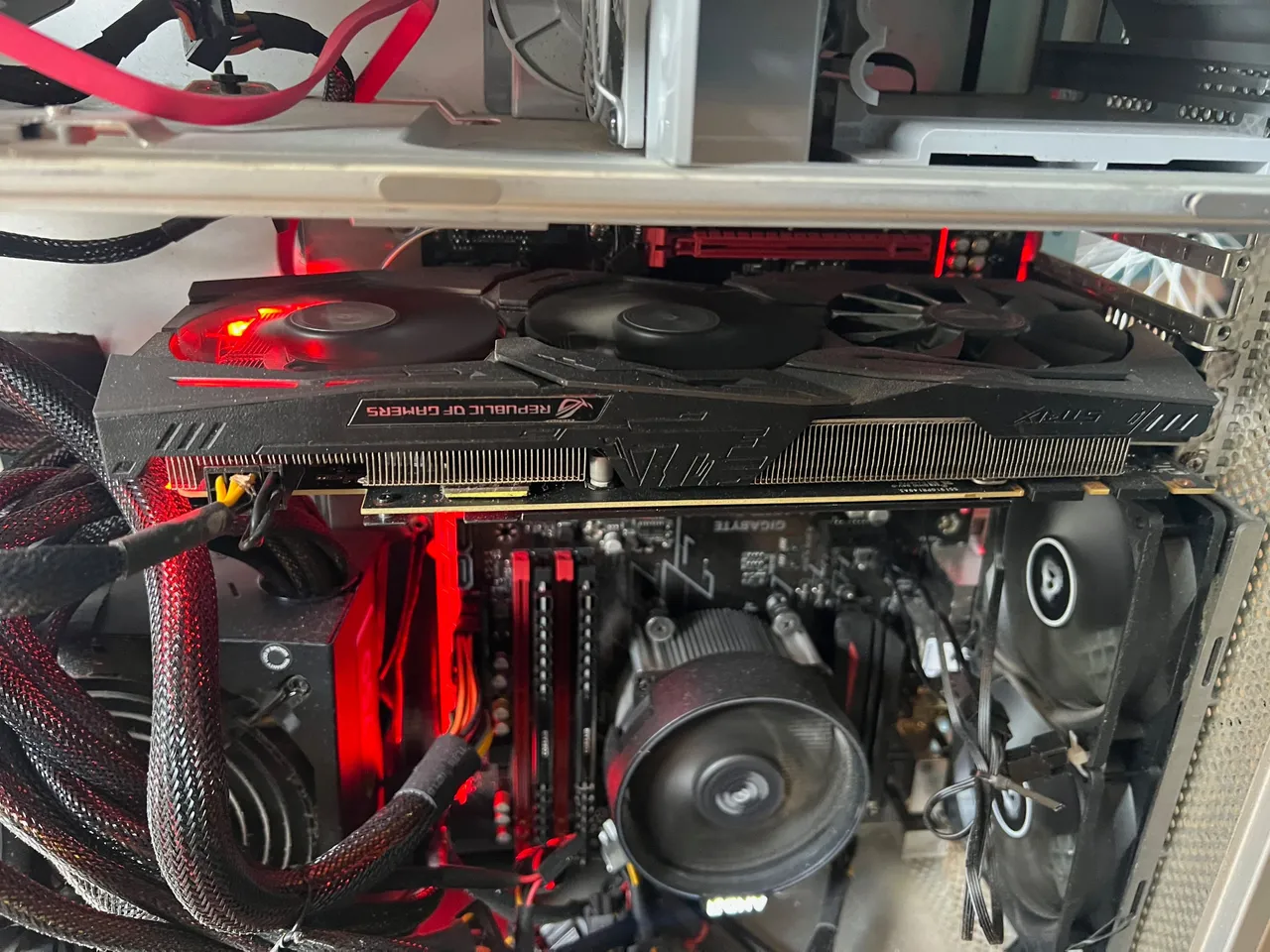
Front fans would be a new challenge, and being eager to get my new system up and running in situation I decided to concentrate on the final challenge first - the Power Supply so I could take it home and get it running. Various methods have been used to fit a standard power supply into the Powermac G5 case - the most extreme stripped the supplies down to boards and rebuilt them to fit in the existing profile of the Powermac module which sit along the full bottom of the case. That’s a ton of work though, and my 750w supply actually fits inside the case fine between the front panel and the motherboard - only problem is how to mount it and make it stable. I could of course epoxy it to the back wall of the case - but given PSU’s can fail removing it would be a challenge! And of course power in is at the back, and this is at the front. My first idea for the power cable was to use the existing supply plug in at the back hot glued in place - and then use a standard PSU cable but cut it and solder the cables to the connector. But in the end I found a really long 3 pin kettle plug the PSU uses with a L fitting at the end - that is rather then the cable coming straight out of the back of the 3 pin plug in - it comes out at the side. This is ideal for sitting the PSU on it, giving an good air space for the air flow out from it, utilising the rubber feet from the existing pc case I stripped the motherboard tray from, when hot glued together they provided a stand for the side opposite to the power in of the PSU so it would sit up right in the case. To keep the whole lot from moving around, some solid Gorilla tape - not ideal but really gravity is pulling it down - the psu cable and rubber feet stand are stopping that and it at least means should the PSU die it can be replaced without too much effort. The plug connector for the PSU just slid through the hole in the back of the case where the existing power connector was - and it was more then long enough for plugging the unit in so that just worked for me - a permanent pc power card rather then removable.
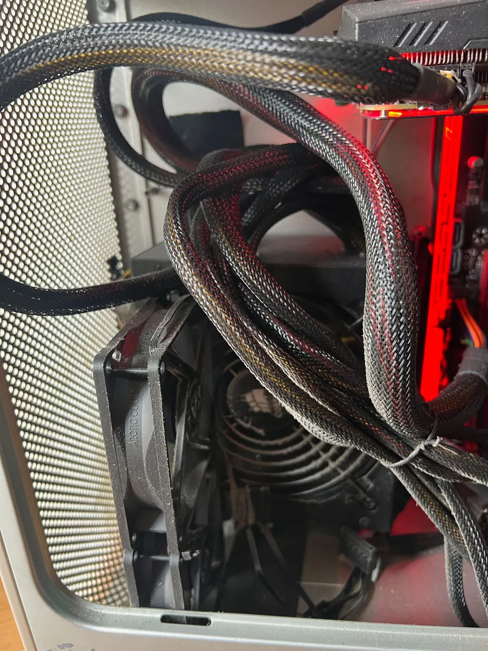
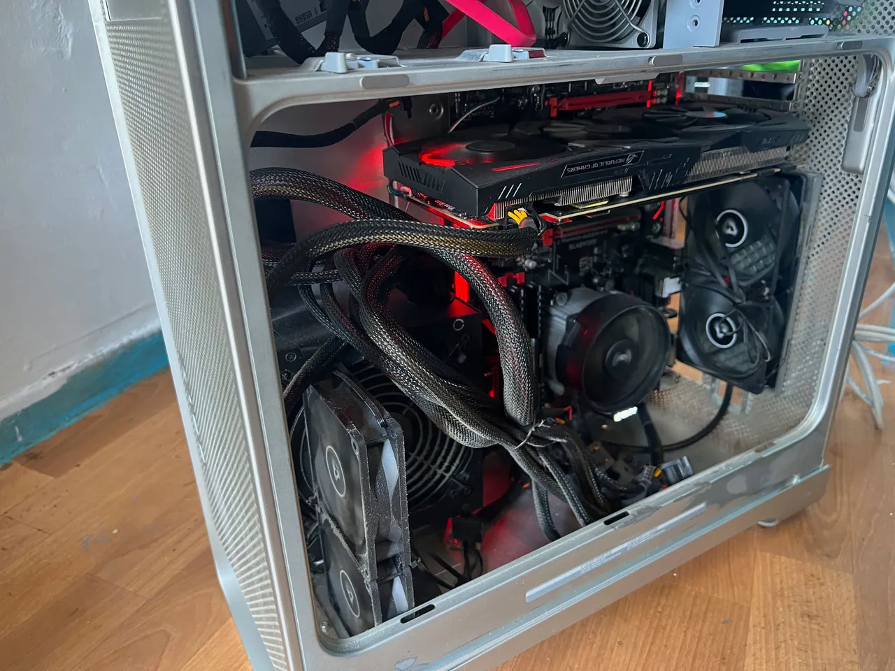
Two things to note here, one this has been used constantly since the end of January so yes there is some dust build up on the fans - I did the cleaning out after the photos! And I know the cable mess is horrible - but the PSU I had spare is fixed cable not modular - so I am stuck with more cables then I need. But as nobody can see inside the PC during use who cares anyway? It has zero effect in temps - in fact this whole case runs incredibly cool considering there is only front to back air flow - I think the aluminium itself acts like a massive heat sink.
With everything rock solid in the case, I was now ready to move it home for in person testing. I might have been more careful then normal with acceleration, breaking and cornering during the drive - bit it arrived safely and with the monitor sat on top of the case (it needed wall mounting which would be weekend job) I could at least finally test it in person. Using Harwareinfo (hwinfo) for keeping an eye on temperatures I started out with a good work out - Far Cry 5. On the whole it worked really well, CPU temps were low 60 degrees while gaming, GPU only hit it’s throttle point of 80 degrees a couple of times - and this was with only two fans at the back sucking hot air out.
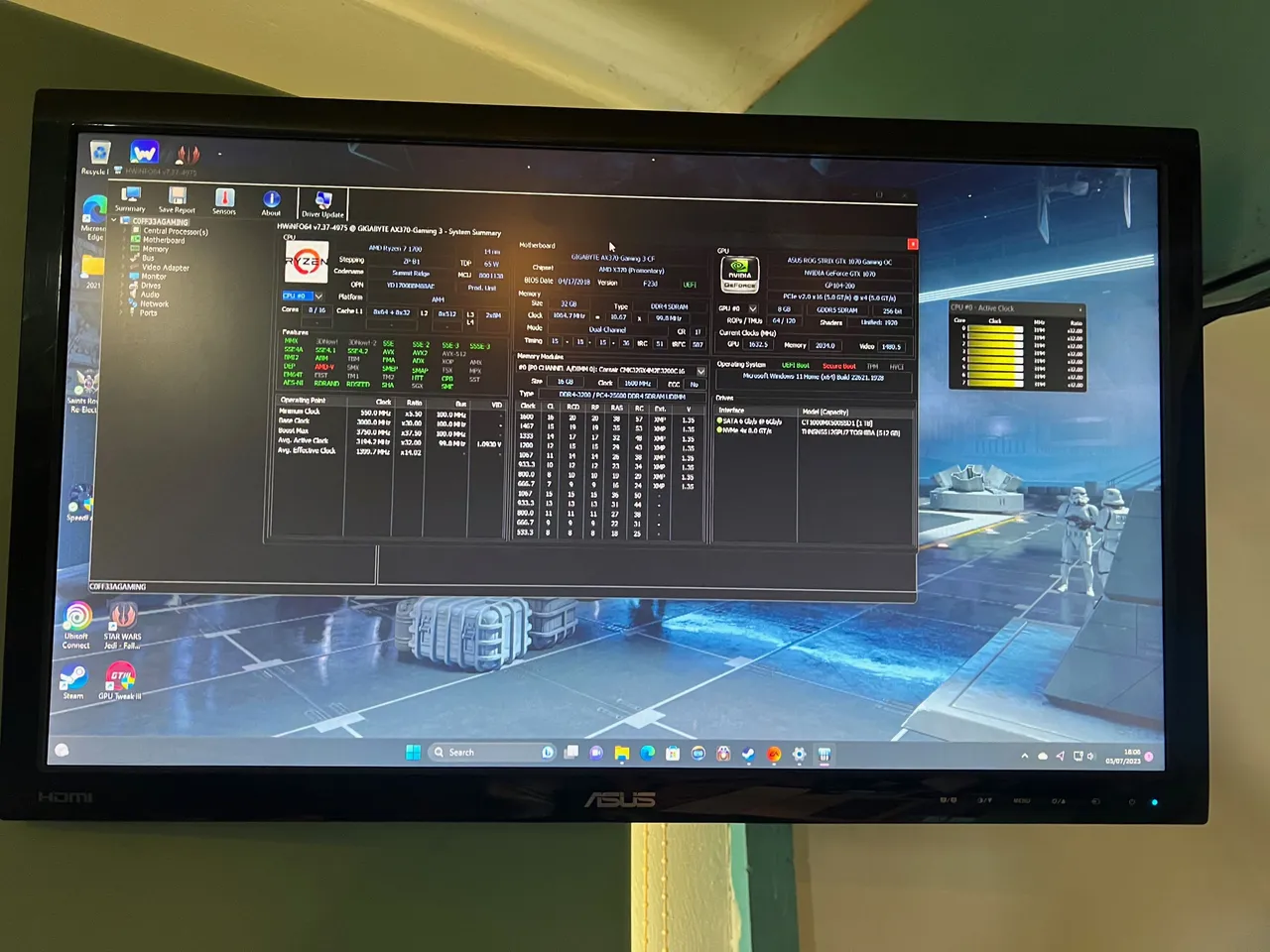
Hardware Info Details
To help with cooling the front fans were going to be essential, so my next job would be try to figure out who to fit them in with no front mounting points. The actual solution was so perfect to be totally unbelievable - the 92mm case fans I selected fitted rock solid tight between the PSU and the lower side of the case - the removable side is recessed enough it does not interfere with them - and when cable tide together stacked and hot glued to the base of the case - they fit nice and solid pulling cool air in from the front of the case - part of which would then be sucked in by the PSU fan to cool it. Plus they are effectively locking the PSU in position - solving it’s mounting as well.
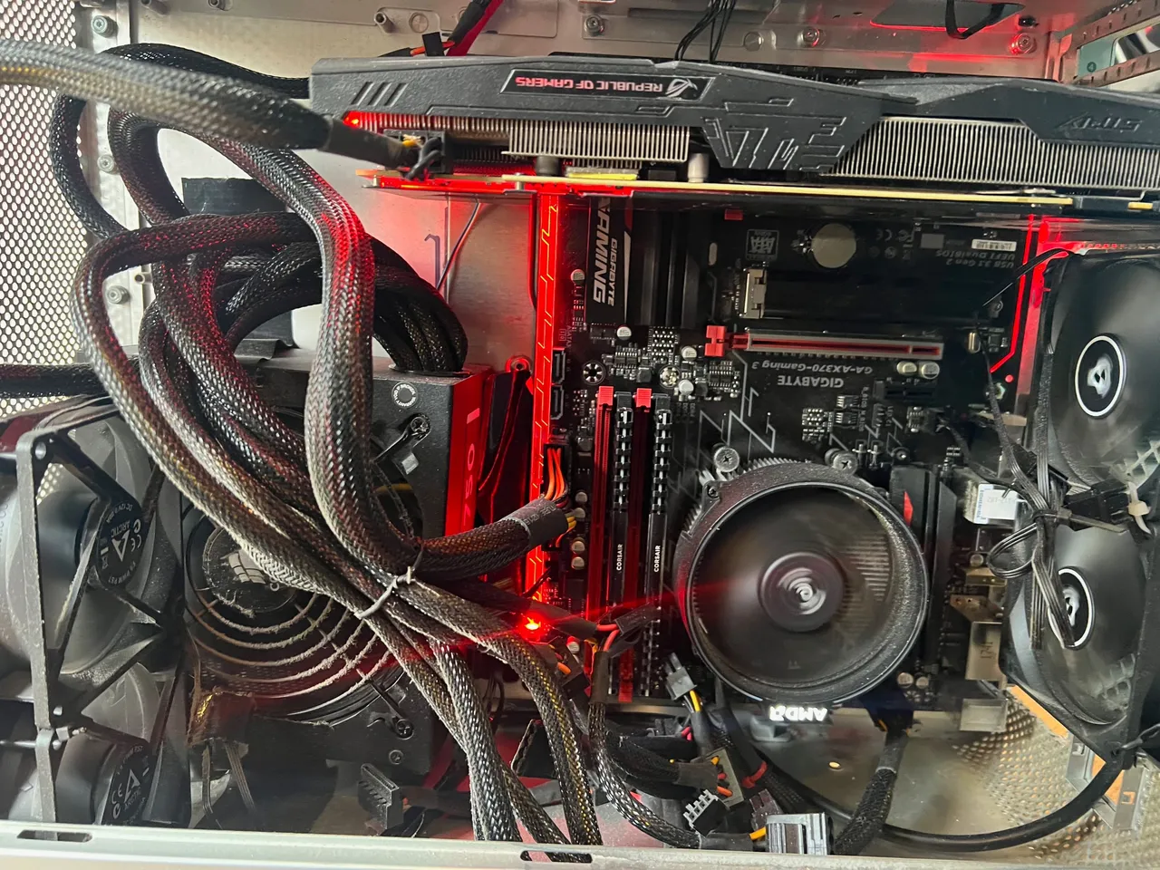
Front fans sit on top of each other connected by cable ties, with a snug fit between them and the PSU / case front there is no movement or vibration. This system runs completely silent all the time, the only fan noise is when I game I force the GPU to 65% fan speed with GPU Tweak III - it's not strictly necessary but when gaming without that the GPU got around 80 degrees alot which was uncomfortable close to throttling temp - with the fans ramped it sits at a cooler 60 degrees.
With the front fans in place further gaming showed temperatures in the case were really good for such a small amount of cooling fans, in fact surprising really. And the whole system is so quiet - hardly any noticeable fan noise. Doom Eternal - on the absolute best the GTX 1070 could handle rarely got the GPU temp even near its throttle limit. This really surprised me, but my theory is the massive chunk of Aluminium the Powermac G5 case is makes it like one big heat sink - while it only has the air in front and air out back compared to modern cases with air inlets often front, back, top, bottom and sometimes one or both sides too - the all metal chassis is a big heat sink compared to modern cases made of mostly plastic, mild steel and some tempered glass.
So everything system wise seemed to be running smoothly, but one unexpected problem proved to be external audio. I expected my 24” gaming monitor to support audio over HDMI which most modern ones do - however going super budget and going for an old used unit showed I had not done my homework enough. Graphics wise it looks and runs great, wall mounted is super convenient making it a nice addition to my home work / play space. And the monitor settings has a volume control - so I was super confused why it remained silent. As a stop gap I had been using a USB speaker for audio, not the best quality but sound at least. Looking up the monitor specifications, it turned out my model never had internal speaker - just an Audio out jack at the back to transfer the HDMI audio to whatever you connect to it. Mildly annoying, but not an issue I went with an inexpensive sound bar for a better quality sound than the single audio usb speaker I had lying around.
https://www.ebay.co.uk/itm/314291354447
For the price the audio quality is great, initially I was using Bluetooth as a convenient method of connecting but for some games the Audio stuttered - I think handling the controller input and audio through the bluetooth was a bit much. So a 3.5mm header cable from the Monitor to the sound bar solved this in an instant. (I did try the PC rear audio out to the sound bar first, but the connector on the motherboard looked a bit chewed up like the previous owner had been plugging in cables a lot - and it struggled to work without interference static)
Wall mounting the monitor was another little work around, I went for a dual swing arm bracket because it had to move left from a recess because the monitor itself partially sits in front of a window. The problem was the mount suits a variety of sizes of monitor, and was so big at the back of mine it obscured the power socket completely. This did not affect the mounting holes, they were fine - just the power plug got in the way of the mount sitting flat because of excess metal on it. With my angle grinder I could have cut the space required out no problem, but I did not have it - so two set’s of mole grips and some bending gave the power cable access while letting all mounting points fit flush to the back.
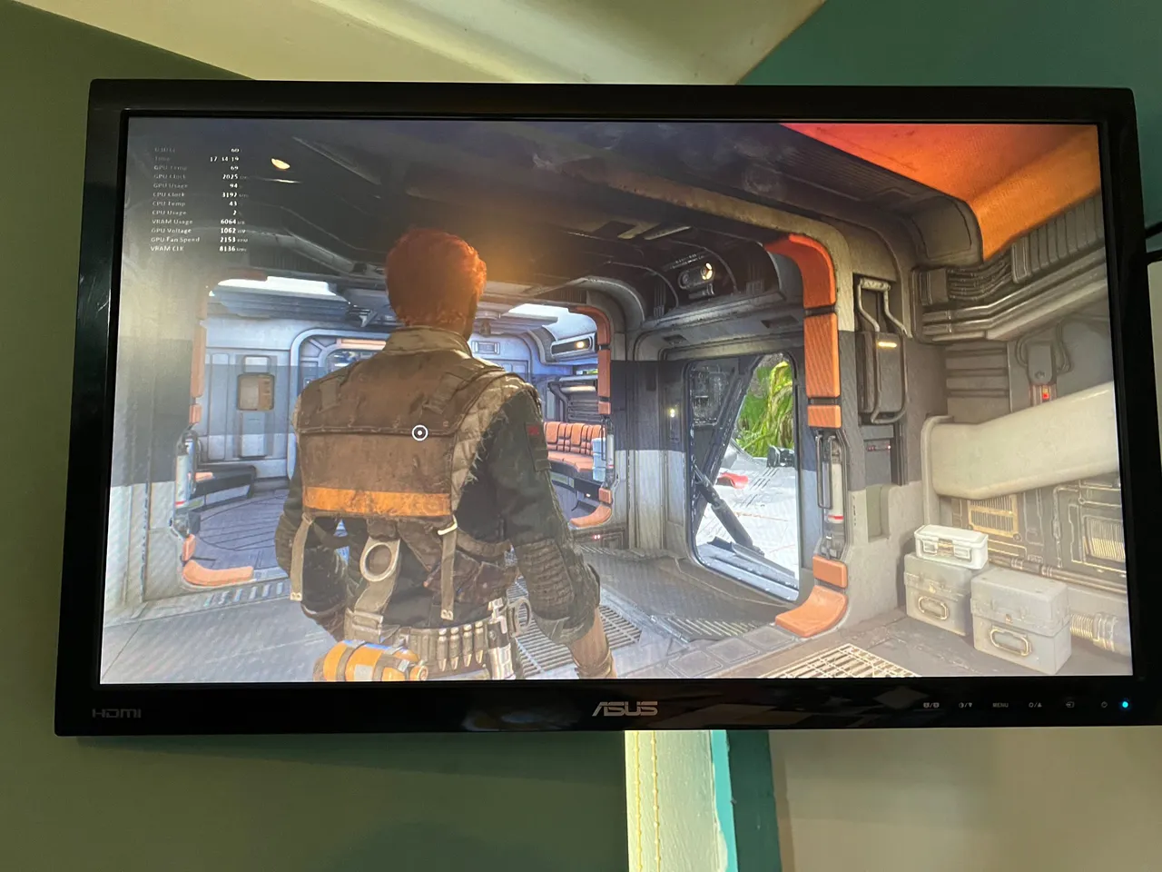
Star Wars Jedi Fallen Order
With everything set up gaming went really well, Forza Horizon 5 looked great and ran a dream, Doom Eternal in all it’s gory glory looked slick, Shadow of Tomb Raider looked visually stunning while running smooth - but of course I had to start looking at FPS stats. I don’t know why really, everything looked great with no stutter, even Far Cry 5 - but then I got this niggle about getting the absolute maximum out of the system and for some weird reason everything seemed to be locked at 50 FPS - and the GTX 1070 should be definitely good for way more then that. Looking up on Google I tried adjusting graphic settings on games that were known to cause FPS slow Downs like shadows - but even setting everyone to low it never went above 50 FPS. Then I went for GPU Tweak III to overclock the graphics card, and to be fair I think some games did look better for it - plus setting the GPU fans at 65% while gaming meant the GPU stayed always a cool 10 to 20 degrees below it’s thermal throttle limit of 80 degrees. But still FPS was stuck at 50 FPS.
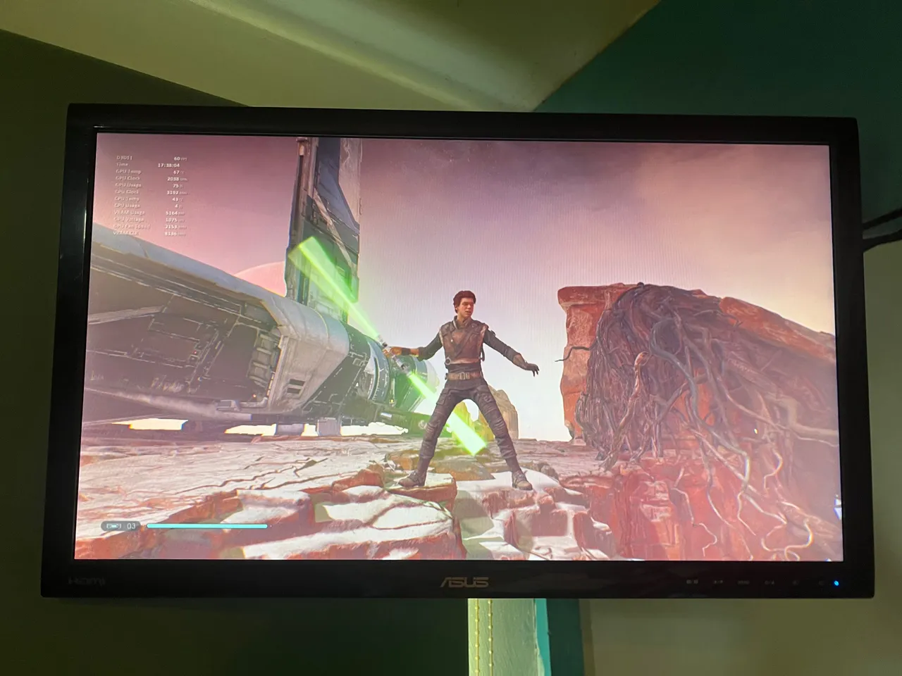
Star Wars Jedi Fallen Order
Needless to say the FPS started to niggle, despite the fact actually playing any game looked great and felt super smooth - no chop or lag it all ran smoothly but knowing the FPS was stuck so low annoyed me. More google work and it seems my amazing budget 24” gaming display is most likely capping it because the refresh rate ties the FPS. A bit more digging and a tool called Custom Resolution Utility allows you to set a custom refresh rate, mine was set at 60hz but a little boost would improve FPS. I tried a few settings, most would just not display anything but 66hz seemed the sweet spot - it still displayed, videos looked good, desktop looked good but more importantly games jumped FPS - some to over 100 FPS - others a solid 60 FPS but they looked good and run smooth for it.
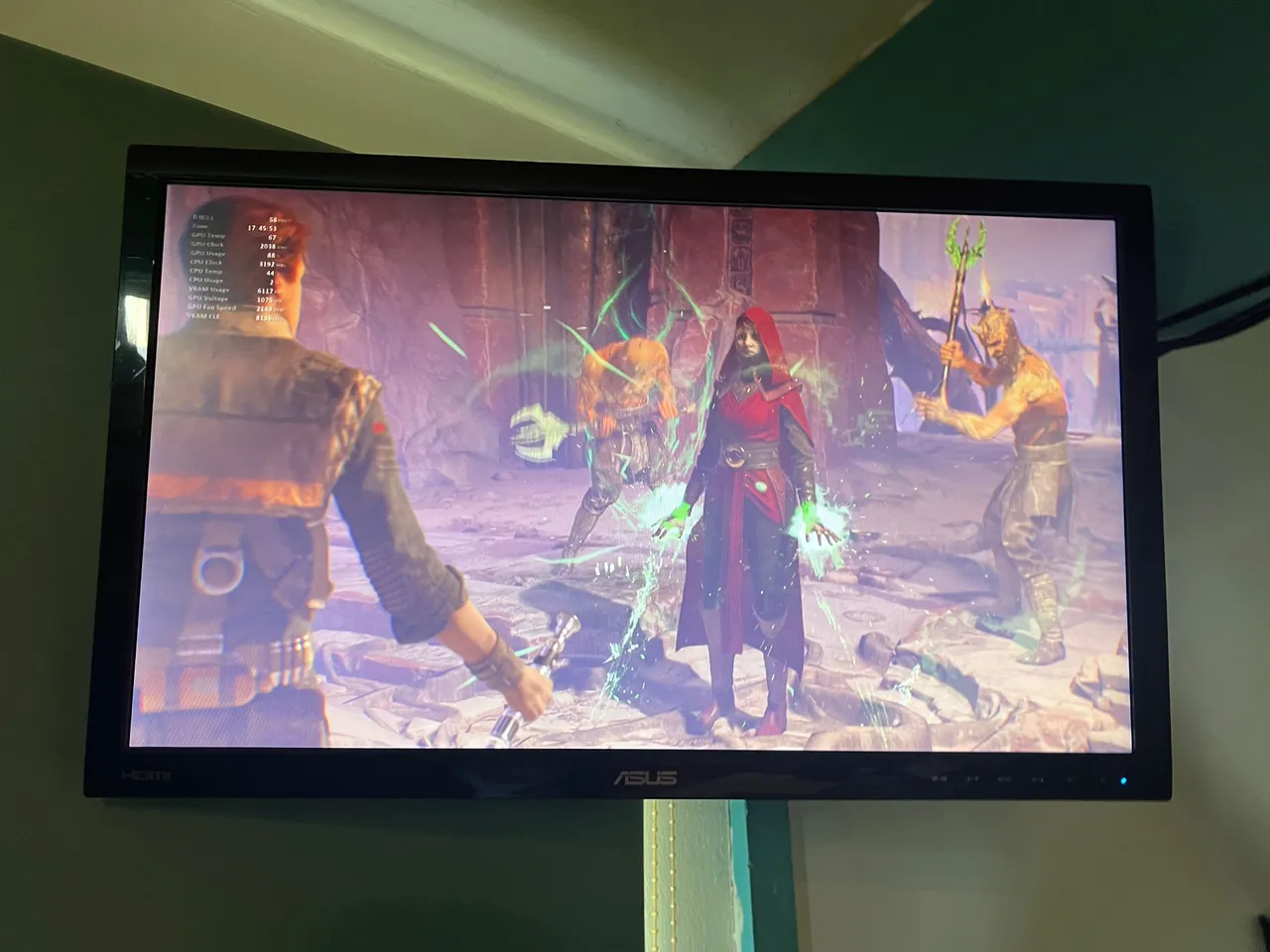
Star Wars Jedi Fallen Order
The end result of all this effort is a gaming pc that runs all the games I want to play super smooth, streams online content from Amazon Prime, Disney +, Netflix, YouTube and Floatplane perfectly and is another handy workhorse computer. But what was the cost.
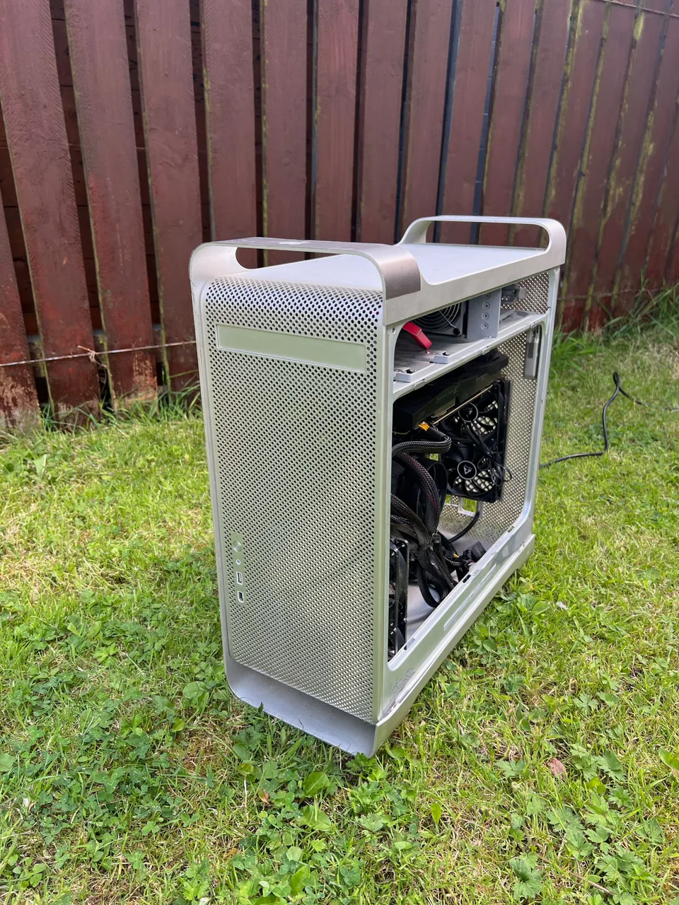
I’m not including the case, I could have saved a lot and made life easier with a stock pc case - but it wouldn’t be a beautiful solid aluminium case from Apple which will withstand anything my household literally throws at it - nothing will protect a pc motherboard like this solid (15kg plus) chunk of aluminium. For reference it was £100 for this 2005 Powermac G5 dead tower.
Motherboard £50 used and with the faulty PCIE slot
CPU £74 with stock led cooler
32gb DDR4 Ram £64.70
GPU £132
Power Supply - no cost I had one lying around.
512gb NVMIE ssd used £37.89
1tb Sata SSD £58.95
CPU Back Plate £6.99
5 Case fans £24.71
Total £449.24
To compare PS5 £449.99 for 825gb (I have 1512gb)
Xbox Series X $449.99 for 1000gb (I have 1512gb)
Now either console might give a better display output (but probably not on my budget 24” display) but crucially I don’t have to buy any games - I just use my boy’s games collection with steam family sharing, Epic and EA - and we have the same taste. So compared to buying a console and then buying games - I have a cheaper system, free games, it streams any content I like and is actually a computer I can use for work, video encoding etc. Plus I can easily increase storage with 4 available SATA ports on the motherboard adding in more SSD's for fast expanded onboard storage is a breeze.
I will admit the internal cables look a mess, but in a case like this you can not see inside so really does it matter. And after 6 months or running constantly they are having no effect on air flow, temps or causing excess dust build up.
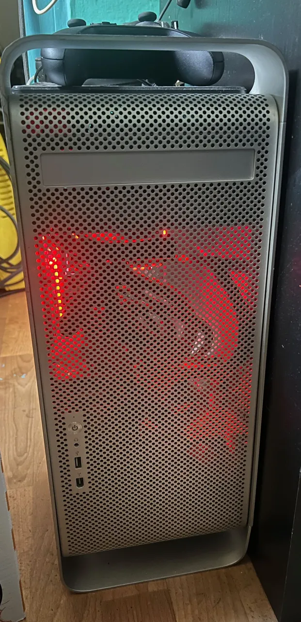
My work around for the power button does mean there is no power on indicator light at the front, but this really does not matter because you can see through the front grill the glowing red of the motherboard LED Lighting, along with the pulsing red of the GPU LED lighting and the white of the CPU cooler LED Lighting. In fact looking at the front with it's pulsing red glow is quite satisfying in the dark. And whatever the brightness in the room, you can definitely tell it is powered up from the red glow inside.
